
Chrysler Stratus Convertible. Manual — part 248
ELECTRICAL NOISE DISTORTION ONE SPEAKER
• Remove output signal connector from (*) ampli-
fier and check for short to ground on the speaker
with the distortion. Refer to Group 8W, Wiring Dia-
grams for the appropriate pin numbers.
• If shorted to ground, disconnect speaker connec-
tor and recheck from the (*) amplifier for short to
ground.
• If still shorted to ground, repair wires. Not
shorted to ground, replace speaker.
• Not shorted to ground, check speaker resistance
at (*) amplifier connector for two to five ohms.
• If resistance is OK, refer to Radio Diagnosis. If
radio checks OK, replace amplifier.
• If resistance is less than two ohms, replace
speaker. If resistance is OK, repair wires
NOTE: (*) From radio if standard system.
MECHANICAL NOISE DISTORTION
• Check trim for loose parts, and speaker attach-
ments for buzzes, repair as necessary.
• Remove speaker while still connected and listen
for distortion. If distortion remains, replace speaker.
ONE SPEAKER NON-OPERATIVE
• Remove connector from (*) amplifier and check
for two to five ohms resistance to the non-operative
speaker. Refer to Group 8W, Wiring Diagrams for the
appropriate pin numbers.
• If resistance is less than two ohms, test speaker
for resistance.
• If OK, refer to Audio Diagnostic Test Procedures.
If not OK, replace speaker.
NOTE: (*) From radio if standard system.
ALL SPEAKERS NON-OPERATIVE
• Check radio for ON state, are the display lights
on
• Radio not ON, refer to Radio Diagnosis
• Check fuses, amplifier connectors and wires for
proper connection
• Check for good ground
• Check amplifier (if equipped with premium sys-
tem), for battery voltage and ON/OFF voltage
(1) Battery voltage OK and NO voltage at the
ON/OFF terminal, check for short or open in the
ON/OFF circuit.
(2) ON/OFF voltage OK, and NO battery voltage,
check for short or open in battery circuit.
(3) Prior to replacing amplifier check fuse 5 in the
Junction Block. If not OK, replace fuse. If fuse blows
again disconnect amplifier B+ wire connector. Refer
to Group 8W, Wiring Diagrams for the proper connec-
tor.
(4) If fuse still blows the problem is not the ampli-
fier. If fuse does not blow replace the amplifier.
(5) If shorted or open circuit repair as necessary.
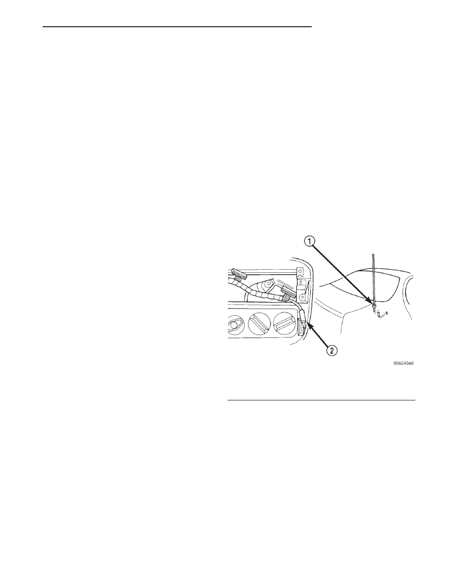
MANUAL ANTENNA
Check for short or open circuits with an ohmmeter
once the antenna cable is disconnected from the
radio. The radio coax cable has a connector that con-
nects behind the between passenger seat and console.
(1) Continuity (less than 1 ohm) should be present
between the antenna mast and radio end pin of
antenna cable plug (Fig. 2).
(2) No continuity should be observed or a very
high resistance of several megohms between the
ground shell of the connector and radio end pin.
(3) Continuity should be observed between the
ground shell of the connector and the mounting hard-
ware in the trunk right rear quarter panel
REMOTE CD CHANGER
CD changer inoperative.
(1) The CD changer receivers its power and
ground through the radio via the DIN connector. Ver-
ify that the radio powers up and functions before pro-
ceeding.
(2) With the radio turned ON, check the radio dis-
play when pushing the MODE/EJECT button to
select the CD mode.
(a) If the display shows “- - - -”, then insert a CD
magazine in the changer.
(b) If the display shows “nocd”, then insert a CD
into the magazine.
(c) If the display shows Err “xxxx”, then check
the error message table below.
Fig. 2 Antenna Test Points
1 – BASE TEST POINT
2 – RADIO TEST POINT
JX
AUDIO SYSTEMS
8F - 13
DIAGNOSIS AND TESTING (Continued)
(d) If the radio only switches between AM and
FM turning modes, then perform the following:
(I) Check the connection of the DIN cable to
the CD changer and radio.
(II) If OK, then check the DIN cable at the CD
changer side.
(III) Make sure the DIN cable is connected to
the radio and radio is turned ON and operating.
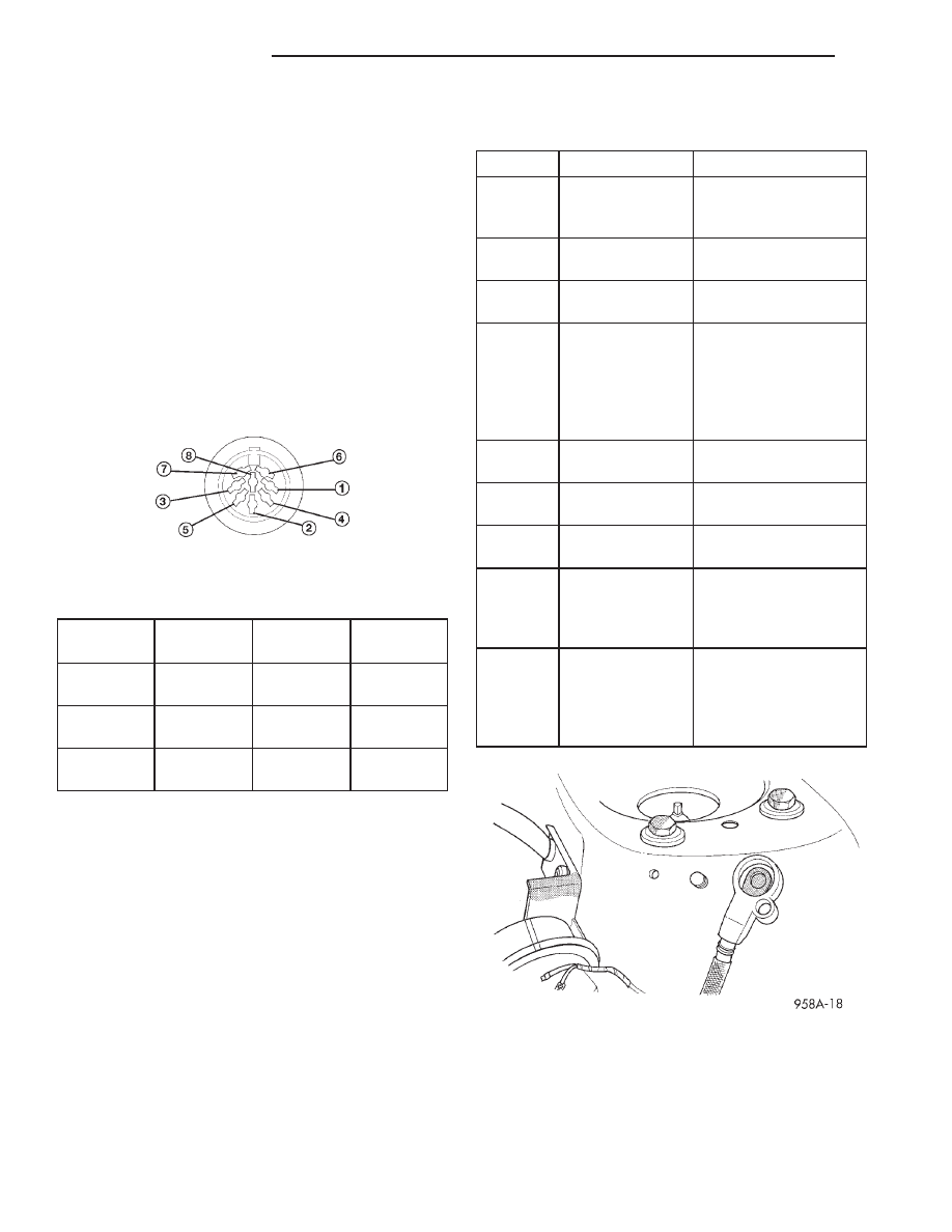
Check for battery voltage at Pins 6 and 7 using
Pin 8 for ground.
(IV) If OK, then replace CD changer.
(V) If not OK, then remove DIN cable from
radio and changer. Check DIN cable for continu-
ity from connector to connector, using a ohmme-
ter on each Pin. If not OK, replace DIN cable.
(VI) If the DIN cable OK, then replace the
radio.
REMOVAL AND INSTALLATION
DOOR MOUNTED SPEAKER
CAUTION: Do not operate the radio with speaker
leads detached. Damage to the output devices may
result.
REMOVAL
(1) Disconnect and isolate the battery negative
remote cable (Fig. 3).
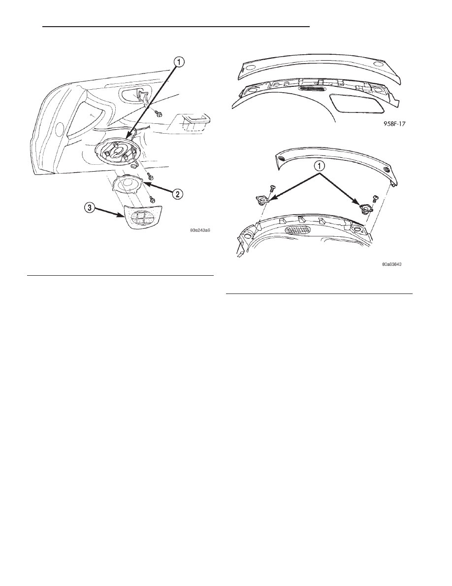
(2) Carefully, pry speaker grille away from door
trim panel (Fig. 4).
(3) Remove four speaker retaining screws.
(4) Pull speaker away from door and disconnect
wiring.
INSTALLATION
For installation reverse above procedures. Ensure
speaker is in the proper position and screws are
tight.
DIN Cable Connector
DIN CABLE PIN-OUTS
PIN 1
DATA BUS
(-)
PIN 5
AUDIO IN
(L)
PIN 2
AUDIO
GRD
PIN 6
BATTERY
PIN 3
DATA BUS
(+)
PIN 7
IGNITION
PIN 4
AUDIO IN
(R)
PIN 8
GROUND
ERROR MESSAGES
DISPLAY
EXPLANATION
WHAT TO DO
NOCD
NO DISC OR
DISCS IN
MAGAZINE
LOAD DISCS IN
MAGAZINE
- - - -
NO MAGAZINE
IN PLAYER
LOAD MAGAZINE IN
PLAYER
ERR
HOT
PLAYER
OVERHEATING
ALLOW TO COOL
DOWN
ERR EE
EE
COMMUNICATION
PROBLEM
TURN IGNITION OFF
TO RESET, CHECK
CABLE
CONNECTION. IF
OK, REPLACE
CHANGER.
ERR
E-01
DEADLOCK
PROBLEM
REPLACE
CHANGER.
ERR
E-02
DISC EJECT
PROBLEM
REPLACE
CHANGER.
ERR
E-06
ELEVATOR
PROBLEM
REPLACE
CHANGER.
ERR
E-07
MAGAZINE
EJECT
PROBLEM
CHECK THAT THE
MAGAZINE IS OK. IF
OK, REPLACE
CHANGER.
ERR
PLAY
DISCS
CANNOT PLAY
CHECK DISC
LOADING, OR TRY
ANOTHER DISC. IF
OK, REPLACE
CHANGER.
Fig. 3 Battery Negative Remote Cable Removal
8F - 14
AUDIO SYSTEMS
JX
DIAGNOSIS AND TESTING (Continued)
INSTRUMENT PANEL SPEAKER
CAUTION: Do not operate the radio with speaker
leads detached. Damage to the output devices may
result.
REMOVAL
(1) Disconnect and isolate the battery negative
remote cable.
(2) Using a trim stick (special tool #C-4755) or
suitable tool, gently pry out and remove both left and
right A-pillar trim moldings.
(3) Remove instrument panel top cover:
(a) Remove screw from right side of the top
cover.
(b) Carefully, pry up each end of top cover to dis-
engage clips (Fig. 5).
(c) Lift rear edge of top cover using a trim stick
along rear edge.
(d) While lifting rear edge slide top cover rear-
ward to disengage front clips and remove the top
cover.
(4) To
remove
speaker,
remove
two
retaining
screws. Lift up speaker and disconnect wire connec-
tor (Fig. 6).
INSTALLATION
For installation, reverse the above procedures.
MANUAL ANTENNA AND MAST
REMOVAL
(1) Inside trunk, pull the right side trunk liner
aside.
(2) Unplug antenna lead from base of antenna
body.
(3) Remove antenna mast by unscrewing mast
from antenna body. Use tape (electrical) to prevent
scratching of the mast base.
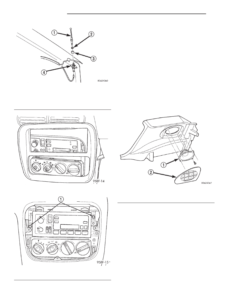
(4) Remove cap nut and adapter (Fig. 7).
(5) Pull antenna body down through the quarter
panel and remove.
INSTALLATION
For installation, reverse the above procedures.
Check that the locating tab is in-line with the slot in
the body before installing antenna. Tighten cap nut
to 7 N·m (65 in. lbs.).
RADIO
REMOVAL
(1) Disconnect and isolate the battery negative
remote cable.
(2) Remove center bezel by pulling straight back
(Fig. 8).
(3) Remove two radio mounting screws (Fig. 9).
Fig. 4 Door Mounted Speaker
1 – FRONT DOOR SPEAKER BRACKET
2 – SPEAKER
3 – GRILLE
Fig. 5 Instrument Panel Top Cover
Fig. 6 Instrument Panel Speakers
1 – SPEAKER
JX
AUDIO SYSTEMS
8F - 15
REMOVAL AND INSTALLATION (Continued)
(4) Pull radio from panel and disconnect wire con-
nectors and antenna lead from radio.
(5) Remove radio from vehicle.
INSTALLATION
For installation, reverse the above procedures.
REAR QUARTER PANEL SPEAKER(S)
CAUTION: Do not operate the radio with speaker
leads detached. Damage to the output devices may
result.
REMOVAL
(1) Disconnect and isolate the battery negative
remote cable (Fig. 3).
(2) Remove rear quarter panel speaker grille.
(3) Remove four retaining screws (Fig. 10).
(4) Disconnect wire connector and remove speaker.
INSTALLATION
For installation reverse the above procedures. Be
sure that the wire connectors are facing rearward in
vehicle, and the screws are tightened.
REMOTE AMPLIFIER
REMOVAL
(1) Disconnect and isolate the battery negative
remote cable.
(2) Remove the right front seat. Refer to Group
23–Body, Manual Front Seat Removal and Installa-
tion.
(3) Remove the two front attaching screws and
loosen the rear retaining nut (Fig. 11) to amplifier.
Fig. 7 Antenna Mounting Removal
1 – MANUAL MAST
2 – ANTENNA NUT
3 – ADAPTER
4 – ANTENNA BASE
Fig. 8 Center Bezel Removal
Fig. 9 Radio Assembly
1 – MOUNTING SCREWS
Fig. 10 Rear Speakers
1 – SPEAKER
2 – GRILLE
8F - 16
AUDIO SYSTEMS
JX
REMOVAL AND INSTALLATION (Continued)
Нет комментариевНе стесняйтесь поделиться с нами вашим ценным мнением.
Текст