
Chrysler Stratus Convertible. Manual — part 220
RADIATOR
CLEANING
Clean radiator fins are necessary for good heat
transfer. The radiator and air conditioning fins
should be cleaned when an accumulation of debris
has occurred. With the engine cold, apply cold water
and compressed air to the back (engine side) of the
radiator to flush the radiator and/or A/C condenser of
debris.
INSPECTION
Inspect the radiator side tanks for cracks, broken
or missing fittings also inspect the joint where the
tanks seam up to the radiator core for signs of leak-
age and/or deteriorating seals.
Inspect radiator core for corroded, bent or missing
cooling fins. Inspect the core for bent or damaged
cooling tubes.
COOLING SYSTEM CLEANING/FLUSHING
CLEANING
CAUTION: Internal
radiator
pressure
must
not
exceed 138 kPa (20 psi) as damage to radiator may
result.
Reverse flushing of cooling system is the forcing of
water through the cooling system. This is done using
air pressure in the opposite direction of normal cool-
ant flow. It is usually only necessary with very dirty
systems with evidence of partial plugging.
(1) Drain cooling system. Remove thermostat hous-
ing and thermostat. Install thermostat housing.
(2) Connect a suitable cooling system flusher and
follow instructions supplied with flusher.
INSPECTION
After performing a flush procedure, inspect all
hoses, clamps and connections for deterioration and
leaks. Inspect radiator and heater core for leaks.
TRANSMISSION OIL COOLER
CLEANING
For cooler flushing procedure, refer to Group 21,
Transaxle.
Clean debris from cooling fins on external (air-to-
oil) cooler as necessary.
INSPECTION
Inspect all hoses, tubes, clamps and connections for
leaks, cracks, or damage. Replace as necessary. Use
only approved transmission oil cooler hoses that are
molded to fit the space available.
Inspect external coolers for leaks, loose mounts, or
damage. Replace as necessary.
ADJUSTMENTS
BELT TENSION GAUGE METHOD
For conventional belts and Poly-V belts, use belt
tensioning gauge Special Tool 7198 to obtain proper
belt tension.
Adjust the belt tension for a New or Used belt as
prescribed in the Belt Tension Chart.
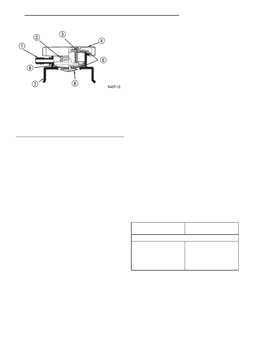
Fig. 36 Cooling System Pressure Cap
1 – OVERFLOW NIPPLE
2 – MAIN SPRING
3 – GASKET RETAINER
4 – STAINLESS-STEEL SWIVEL TOP
5 – RUBBER SEALS
6 – VENT VALVE
7 – THERMOSTAT HOUSING/ENGINE OUTLET CONNECTOR
8 – FILLER NECK
BELT TENSION CHART
ACCESSORY DRIVE
BELTS
GAUGE
2.5L ENGINE
Air Conditioning
Compressor & Generator
Belt
New Belt: 667 N (150
lbs.)
Power Steering Pump
Belt
Used Belt: 356 N (80
lbs.)
JX
COOLING SYSTEM
7 - 27
CLEANING AND INSPECTION (Continued)
SPECIFICATIONS
COOLING SYSTEM CAPACITY
TORQUE
SPECIAL TOOLS
COOLING SYSTEM
ENGINE
CAPACITY
2.5L
10.0* Liters
(10.5* Quarts)
* CAPACITY, Includes Heater and Coolant Recovery
System
DESCRIPTION
N·m
Ft.
Lbs.
In.
Lbs.
A/C Condenser to Radiator—
Fasteners
5
—
45
Thermostat Housing
2.5L—Bolts
19
—
168
Water Pump Mounting
2.5L—Bolts
24
—
205
Water Pump Inlet Tube to
Block—Bolts
12
—
105
Water Pump Inlet Pipe to
Cylinder Head 2.5L—
Fasteners
14
—
123
Fan Module to Radiator—
Fasteners
7
—
65
Fan Motor to Shroud—
Fasteners
5
—
45
Transmission Oil Cooler
Hose—Clamps
2
—
18
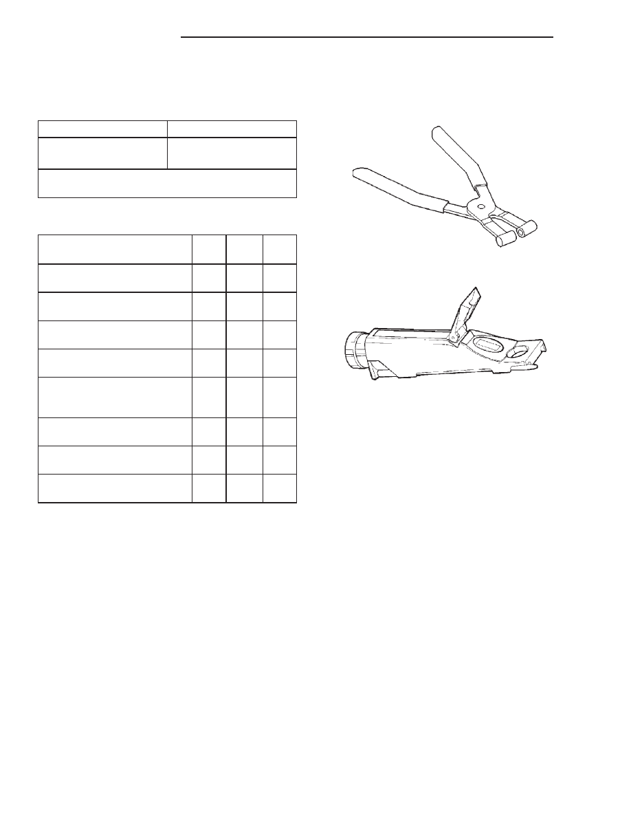
Hose Clamp Pliers 6094
Coolant Refractometer 8286
7 - 28
COOLING SYSTEM
JX
COOLING SYSTEM
TABLE OF CONTENTS
page
page
DESCRIPTION AND OPERATION
. . . . . . . . . . . . . . . . . . . . . . 1
COOLANT . . . . . . . . . . . . . . . . . . . . . . . . . . . . . . 2
ENGINE THERMOSTAT—2.0L ENGINE
WATER PUMP—2.0L ENGINE . . . . . . . . . . . . . . 3
COOLANT RECOVERY SYSTEM
. . . . . . . . . . . . . . . . . . . . . . . . . 4
. . . . . . . . . . . . . . . . . . 4
. . . . . . . . . . . . . . . . . . . . . . . . . . . . . 4
. . . . . . . . . . . . . . . . . 5
COOLING SYSTEM PRESSURE CAP . . . . . . . . . 5
TRANSMISSION OIL COOLER EXTERNAL—
2.0L ENGINE . . . . . . . . . . . . . . . . . . . . . . . . . . . 5
. . . . . . . . . . . . . . . . . 6
DIAGNOSIS AND TESTING
. . . . . . . . . . . . . . . . . . . . . . . . . 12
. . . . . . . . . . . . . . . 12
COOLING SYSTEM FLOW CHECK . . . . . . . . . . 12
RADIATOR FAN CONTROL
. . . . . . . . . . . . . . . 13
COOLING SYSTEM LEAK TESTING . . . . . . . . . 14
COOLING SYSTEM PRESSURE RELIEF
CHECK . . . . . . . . . . . . . . . . . . . . . . . . . . . . . . . 14
COOLING SYSTEM PRESSURE CAP . . . . . . . . 15
LOW COOLANT LEVEL AERATION
TRANSAXLE OIL COOLER FLOW CHECK
. . . . . . . . . . . . . . . . 15
. . . . . . . . . . . . . . . . . 16
SERVICE PROCEDURES
COOLANT—ADDING ADDITIONAL. . . . . . . . . . . 16
COOLANT LEVEL SERVICING—2.0L ENGINE . . 16
COOLING SYSTEM—DRAINING. . . . . . . . . . . . . 16
COOLING SYSTEM—REFILLING . . . . . . . . . . . . 17
REMOVAL AND INSTALLATION
WATER PUMP—2.0L ENGINES . . . . . . . . . . . . . 17
WATER PUMP INLET TUBE—2.0/2.4L
. . . . . . . . . . . . . . . . . . . . . . . . . . . . . . . 18
THERMOSTAT—2.0L ENGINE . . . . . . . . . . . . . . 18
RADIATOR . . . . . . . . . . . . . . . . . . . . . . . . . . . . . 19
RADIATOR DRAINCOCK . . . . . . . . . . . . . . . . . . . 20
RADIATOR FAN, MOTOR AND SHROUD . . . . . . 21
TRANSMISSION OIL COOLER EXTERNAL—
. . . . . . . . . . . . . . . . . . . . . . . . . . . . 21
CLEANING AND INSPECTION
WATER PUMP—2.0L ENGINES . . . . . . . . . . . . . 23
ACCESSORY DRIVE BELT. . . . . . . . . . . . . . . . . . 23
COOLING SYSTEM PRESSURE CAP . . . . . . . . . 23
RADIATOR . . . . . . . . . . . . . . . . . . . . . . . . . . . . . 24
COOLING SYSTEM . . . . . . . . . . . . . . . . . . . . . . . 24
TRANSAXLE OIL COOLER . . . . . . . . . . . . . . . . . 24
ADJUSTMENTS
BELT TENSION GAUGE METHOD . . . . . . . . . . . . 25
SPECIFICATIONS
SPECIAL TOOLS
COOLING SYSTEM . . . . . . . . . . . . . . . . . . . . . . . 25
DESCRIPTION AND OPERATION
COOLING SYSTEM
DESCRIPTION
The cooling system consists of an engine cooling
module, thermostat, coolant, a water pump to circu-
late the coolant. The engine cooling module may con-
sist of a radiator, electric fan motor, shroud, radiator
pressure cap, coolant reserve system, transmission
oil cooler and lines, hoses, clamps, and air condition-
ing condenser.
OPERATION
The primary purpose of a cooling system is to
maintain engine temperature in a range that will
provide satisfactory engine performance and emission
levels under all expected driving conditions. It also
JX
COOLING SYSTEM
7 - 1
provides hot water (coolant) for heater performance
and cooling for automatic transmission oil. It does
this by transferring heat from engine metal to cool-
ant, moving this heated coolant to the radiator, and
then transferring this heat to the ambient air.
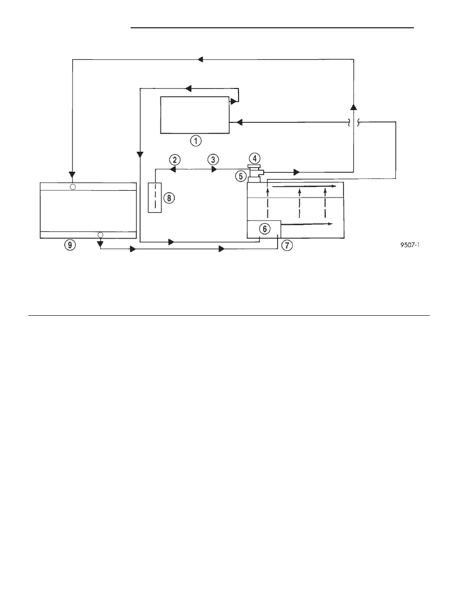
The coolant flow circuits for 2.0L engine equipped
vehicles are shown in (Fig. 1).
COOLANT
DESCRIPTION
ETHYLENE-GLYCOL MIXTURES
CAUTION: Richer antifreeze mixtures cannot be
measured with normal field equipment and can
cause problems associated with 100 percent ethyl-
ene-glycol.
The required ethylene-glycol (antifreeze) and water
mixture depends upon the climate and vehicle oper-
ating conditions. The recommended mixture of 50/50
ethylene-glycol and water will provide protection
against freezing to -37 deg. C (-35 deg. F). The anti-
freeze concentration must always be a minimum of
44 percent, year-round in all climates. If percentage
is lower than 44 percent, engine parts may be
eroded by cavitation, and cooling system com-
ponents may be severely damaged by corrosion.
Maximum protection against freezing is provided
with a 68 percent antifreeze concentration, which
prevents freezing down to -67.7 deg. C (-90 deg. F). A
higher percentage will freeze at a warmer tempera-
ture. Also, a higher percentage of antifreeze can
cause the engine to overheat because the specific
heat of antifreeze is lower than that of water.
Use of 100 percent ethylene-glycol will cause for-
mation of additive deposits in the system, as the cor-
rosion inhibitive additives in ethylene-glycol require
the presence of water to dissolve. The deposits act as
insulation, causing temperatures to rise to as high as
149 deg. C (300) deg. F). This temperature is hot
enough to melt plastic and soften solder. The
increased temperature can result in engine detona-
tion. In addition, 100 percent ethylene-glycol freezes
at 22 deg. C (-8 deg. F ).
PROPYLENE-GLYCOL MIXTURES
It’s overall effective temperature range is smaller
than that of ethylene-glycol. The freeze point of 50/50
propylene-glycol and water is -32 deg. C (-26 deg. F).
5 deg. C higher than ethylene-glycol’s freeze point.
The boiling point (protection against summer boil-
Fig. 1 Cooling System Operation—2.0L Engine
1 – HEATER
2 – HEAT UP
3 – COOL DOWN
4 – PRESSURE CAP
5 – THERMOSTAT HOUSING
6 – WATER PUMP
7 – ENGINE
8 – COOLANT RECOVERY SYSTEM TANK
9 – RADIATOR
7 - 2
COOLING SYSTEM
JX
DESCRIPTION AND OPERATION (Continued)
Нет комментариевНе стесняйтесь поделиться с нами вашим ценным мнением.
Текст