
Chrysler Stratus Convertible. Manual — part 219
(2) Reverse the above procedure for Installation.
Tighten fan motor fasteners to 5 N·m (45 in. lbs.).
INSTALLATION
(1) Install fan module to radiator. Tighten shroud
to radiator fasteners to 7.5 N·m (65 in. lbs.).
(2) Connect fan motor lead. For wiring diagrams
of fan motor systems refer to Group, 8W Wiring
Diagrams.
(3) Install upper radiator crossmember. Refer to
Group 23, Body for procedure.
COOLANT RECOVERY BOTTLE
REMOVAL
(1) Disconnect coolant hose from bottle.
(2) Remove bottle attaching screws (Fig. 28).
(3) Remove bottle (Fig. 28).
INSTALLATION
(1) Position bottle and install attaching screws
(Fig. 28). Tighten screws to 4.6 N·m (40 in. lbs.).
(2) Connect coolant hose to bottle.
ENGINE BLOCK HEATER
REMOVAL
(1) Drain coolant from radiator and cylinder block.
Refer to Cooling System Drain, Clean, Flush and
Refill of this section for procedure.
(2) Detach power cord plug from heater.
(3) Loosen screw in center of heater. Remove
heater assembly.
INSTALLATION
(1) Thoroughly clean core hole and heater seat
(Fig. 29).
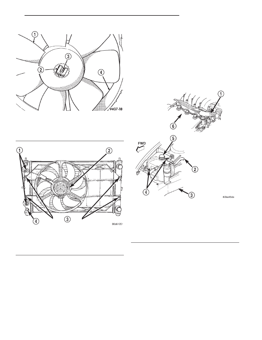
Fig. 26 Radiator Fan—Removal
1 – FAN
2 – RETAINING CLIP
3 – MOTOR SHAFT
4 – SHROUD ASSEMBLY
Fig. 27 Fan Module
1 – TRANSMISSION OIL COOLER
2 – SINGLE FAN
3 – FAN MODULE FASTENERS
4 – DRAINCOCK
Fig. 28 Coolant Recovery Bottle
1 – TO CRS BOTTLE
2 – TO ENGINE
3 – RIGHT FRAME RAIL
4 – SCREWS (2) 4.6 N·m (40 in. lbs.)
5 – COOLANT RECOVERY SYSTEM (CRS) BOTTLE
6 – 2.5L ENGINE
7 – FWD
JX
COOLING SYSTEM
7 - 23
REMOVAL AND INSTALLATION (Continued)
(2) Insert heater assembly with electrical connec-
tor position at the top of the core hole.
(3) With
heater
seated,
tighten
center
screw
securely to assure a positive seal.
(4) Fill cooling system with coolant to the proper
level, vent air, and inspect for leaks. Pressurize sys-
tem with Radiator Pressure Tool before looking for
leaks.
The power cord must be secured in its retainer
clips, and not positioned so it could contact linkages
or exhaust manifolds and become damaged.
ACCESSORY DRIVE BELTS
AIR CONDITIONING AND GENERATOR BELT
REMOVAL
(1) Remove power steering pump drive belt. Refer
to procedure in this section.
(2) Loosen idler pulley locking bolt (Fig. 31).
(3) Loosen the adjusting screw to decrease the
idler pulley tension (Fig. 31).
(4) Remove belt.
INSTALLATION
(1) Refer to (Fig. 30) for belt routing.
(2) Install drive belt on pulleys.
NOTE: Use Special Tool 7198, Belt Tension Gauge
to check belt for proper tension.
(3) Tighten the adjusting screw until belt is ten-
sioned to specifications. Refer to Belt Tension Chart
for specifications.
(4) Tighten idler pulley locking bolt to 54 N·m (40
ft. lbs.). Recheck belt for proper tension and adjust as
necessary.
(5) Install power steering pump drive belt.
Air Conditioning and Generator Belt Tension Adjustment
To adjust the air conditioning and generator drive
belt, loosen the idler pulley locking bolt and adjust
belt tension by turning adjusting screw (Fig. 31). Use
Belt Tension Gauge and refer to Belt Tension Chart
for specification. Tighten pulley bolt to 54 N·m (40 ft.
lbs.) after adjustment.
POWER STEERING PUMP BELT
REMOVAL
(1) From the top of the vehicle loosen pivot bolt
(Fig. 33).
(2) Hoist vehicle and remove splash shield (Fig.
32).
(3) From under the vehicle loosen the locking bolts
F and G (Fig. 33).
INSTALLATION
(1) Install belt. Refer to (Fig. 30) for belt routing.
NOTE: Use Special Tool 7198, Belt Tension Gauge
to check belt for proper tension.
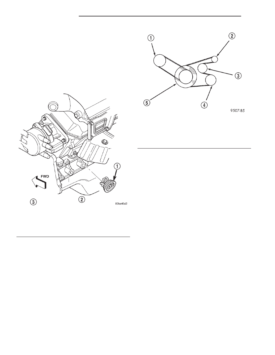
Fig. 29 Engine Block Heater
1 – BLOCK HEATER
2 – 2.5L ENGINE
3 – LEFT REAR SIDE VIEW
4 – FWD
Fig. 30 Accessory Drive Belt Routing—2.5L Engine
1 – POWER STEERING PUMP
2 – GENERATOR
3 – IDLER
4 – AIR CONDITIONING COMPRESSOR
5 – CRANKSHAFT DAMPER
7 - 24
COOLING SYSTEM
JX
REMOVAL AND INSTALLATION (Continued)
(2) Adjust belt tension with 1/2 in. drive breaker
bar installed in adjusting bracket (Fig. 33). Use belt
tension gauge and refer to Belt Tension Chart for
tension specification.
(3) Tighten locking bolt G to 28 N·m (250 in. lbs.)
(Fig. 33).
(4) Tighten locking bolt F and the pivot bolt to 54
N·m (40 ft. lbs.).
Power Steering Pump Belt Tension Adjustment
Refer to Power Steering Pump Belt installation
procedures for belt tensioning procedures.
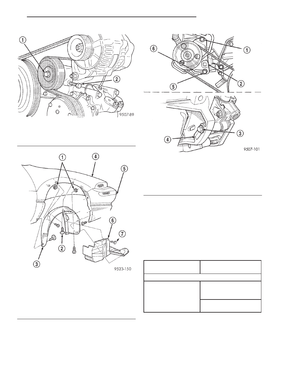
Fig. 31 Air Conditioning Compressor and Generator
Belt Idler
1 – LOCKING BOLT
2 – ADJUSTING BOLT
Fig. 32 Accessory Drive Belt Splash Shield
1 – NUT-SNAP
2 – PUSH-IN FASTENER
3 – WHEELHOUSE SPLASH SHIELD
4 – FENDER
5 – FASCIA
6 – ACCESSORY DRIVE BELT SPLASH SHIELD
7 – PUSH-IN FASTENER
Fig. 33 Power Steering Belt Adjustment
1 – PIVOT BOLT
2 – 1/2 INCH SQUARE OPENING
3 – LOCKING BOLT (G)
4 – ADJUSTMENT SLOT
5 – LOCKING BOLT (F)
6 – ADJUSTMENT SLOT
BELT TENSION CHART
ACCESSORY DRIVE
BELTS
GAUGE
2.5L ENGINE
Air Conditioning
Compressor &
Generator Belt
New
Belt:
667 N (150 lbs.)
Power Steering Pump
Belt
Used
Belt:
356 N (80 lbs.)
JX
COOLING SYSTEM
7 - 25
REMOVAL AND INSTALLATION (Continued)

CLEANING AND INSPECTION
WATER PUMP—2.5L ENGINE
CLEANING
Clean all gasket mating surfaces as necessary.
INSPECTION
Replace the water pump if it has any of the follow-
ing defects:
• Damage or cracks on the pump body.
• Coolant leaks, if the shaft seal is leaking, evi-
dent by traces of coolant leaks from vent hole “A” in
(Fig. 34).
• Impeller rubs inside of pump.
• Excessively loose or rough turning bearing.
ACCESSORY DRIVE BELT
CLEANING
Clean all foreign debris from belt pulley grooves.
The belt pulleys must be free of oil, grease, and cool-
ants before installing the drive belt.
INSPECTION
Belt replacement under any or all of the following
conditions is required:
• Excessive wear
• Frayed cords
• Severe glazing
Poly-V Belt system may develop minor cracks
across the ribbed side. These minor cracks are con-
sidered normal and acceptable. Cracks parallel are
not (Fig. 35).
NOTE: Do not use any type of belt dressing or
restorer on Poly-V Belts.
COOLING SYSTEM PRESSURE CAP
CLEANING
Use only a mild soap to clean the pressure cap.
INSPECTION
Hold the cap in your hand, right side up (Fig. 36).
The vent valve at the bottom of the cap should open.
If the rubber gasket has swollen, preventing the
valve from opening, replace the cap.
Hold the cleaned cap in your hand, upside down.
If any light can be seen between vent valve and the
rubber gasket, replace the cap. Do not use a
replacement cap that has a spring to hold the
vent shut.
A replacement cap must be of the type designed for
coolant reserve systems. This design ensures coolant
return to the radiator.
Fig. 34 Water Pump Inspection
1 – PUMP HOUSING INLET
Fig. 35 Drive Belt Wear Pattern
1 – NORMAL CRACKS BELT OK
2 – NOT NORMAL CRACKS REPLACE BELT
7 - 26
COOLING SYSTEM
JX
Нет комментариевНе стесняйтесь поделиться с нами вашим ценным мнением.
Текст