
Chrysler Stratus Convertible. Manual — part 69
from four sense circuits. The TCM interprets this
information and determines the appropriate tran-
saxle gear position and shift schedule.
Since there are four switches, there are 16 possible
combinations of open and closed switches (codes).
Seven of these codes are related to gear position and
three are recognized as “between gear” codes. This
results in six codes which should never occur. These
are called “invalid” codes. An invalid code will result
in a DTC, and the TCM will then determine the shift
lever position based on pressure switch data. This
allows reasonably normal transmission operation
with a TRS failure.
TRANSMISSION TEMPERATURE SENSOR
The TRS has an integrated thermistor (Fig. 18)
that the TCM uses to monitor the transmission’s
sump temperature. Since fluid temperature can
affect transmission shift quality and convertor lock
up, the TCM requires this information to determine
which shift schedule to operate in. The PCM also
monitors this temperature data so it can energize the
vehicle cooling fan(s) when a transmission “overheat”
condition exists. If the thermistor circuit fails, the
TCM will revert to calculated oil temperature usage.
CALCULATED TEMPERATURE
A failure in the temperature sensor or circuit will
result in calculated temperature being substituted for
actual temperature. Calculated temperature is a pre-
dicted fluid temperature which is calculated from a
combination of inputs:
• Battery (ambient) temperature
• Engine coolant temperature
• In-gear run time since start-up
INPUT SPEED SENSOR
DESCRIPTION
The Input Speed Sensor is a two-wire magnetic
pickup device that generates AC signals as rotation
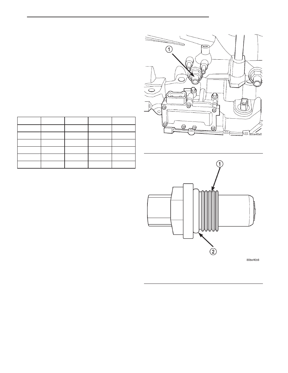
occurs. It is threaded into the transaxle case (Fig.
19), sealed with an o-ring (Fig. 20), and is considered
a primary input to the Transmission Control Module
(TCM).
OPERATION
The Input Speed Sensor provides information on
how fast the input shaft is rotating. As the teeth of
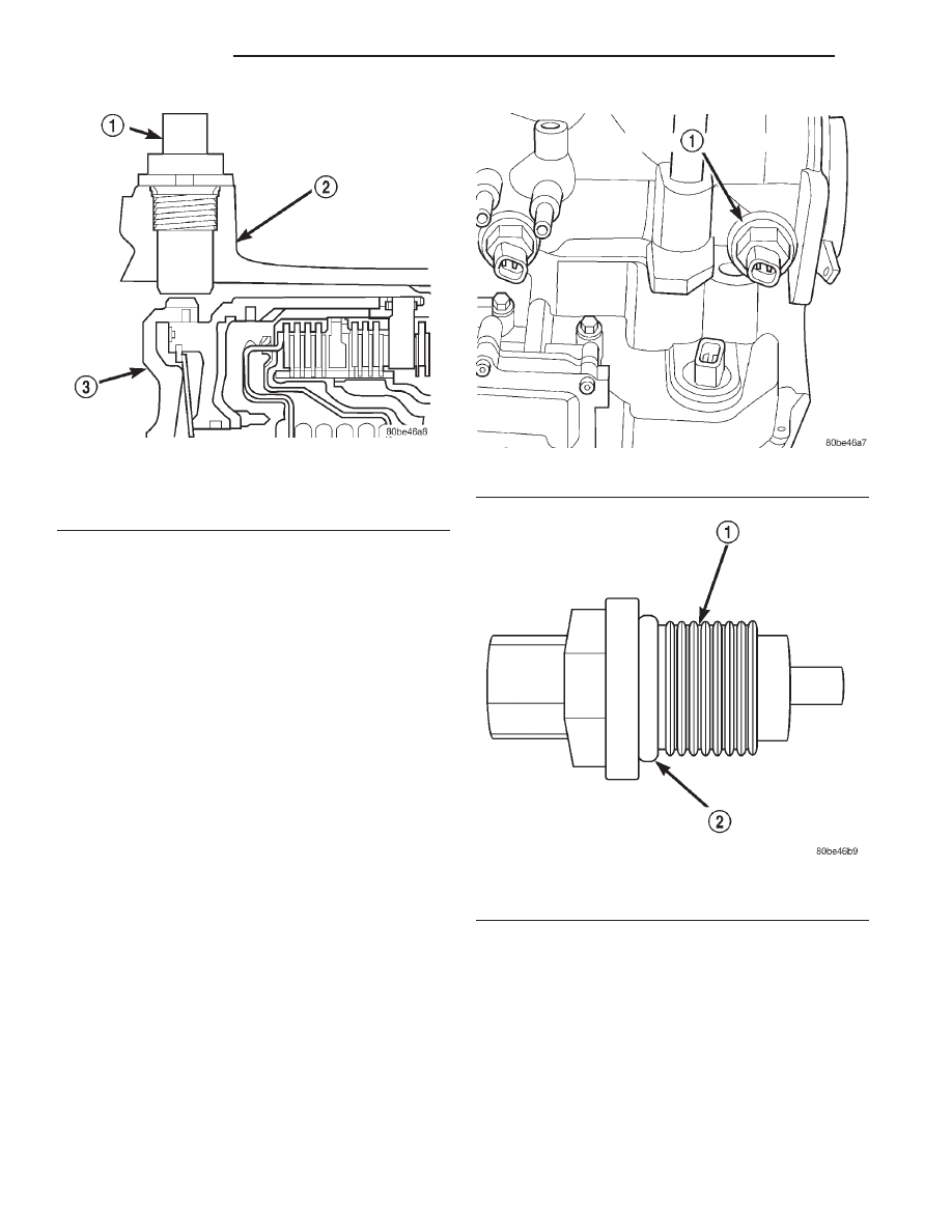
the input clutch hub pass by the sensor coil (Fig. 21),
an AC voltage is generated and sent to the TCM. The
TCM interprets this information as input shaft rpm.
The TCM compares the input speed signal with
output speed signal to determine the following:
• Transmission gear ratio
• Speed ratio error detection
• CVI calculation
TRS SWITCH STATES
SLP
T42
T41
T3
T1
P
CL
CL
CL
OP
R
CL
OP
OP
OP
N
CL
CL
OP
CL
OD
OP
OP
OP
CL
3 (AS)
OP
OP
CL
OP
L
CL
OP
CL
CL
Fig. 19 Input Speed Sensor Location
1 – INPUT SPEED SENSOR
Fig. 20 O-Ring Location
1 – INPUT SPEED SENSOR
2 – O-RING
JX
TRANSAXLE
21 - 15
DESCRIPTION AND OPERATION (Continued)
The TCM also compares the input speed signal and
the engine speed signal to determine the following:
• Torque converter clutch slippage
• Torque converter element speed ratio
OUTPUT SPEED SENSOR
DESCRIPTION
The Output Speed Sensor is a two-wire magnetic
pickup device that generates an AC signal as rotation
occurs. It is threaded into the transaxle case (Fig.
22), sealed with an o-ring (Fig. 23), and is considered
a primary input to the Transmission Control Module
(TCM).
OPERATION
The Output Speed Sensor provides information on
how fast the output shaft is rotating. As the rear
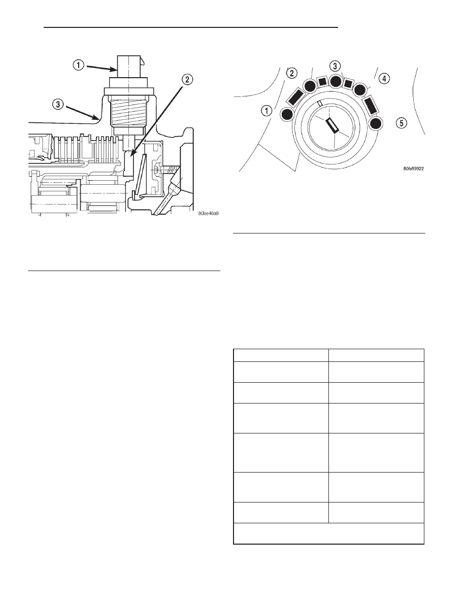
planetary carrier park pawl lugs pass by the sensor
coil (Fig. 24), an AC voltage is generated and sent to
the TCM. The TCM interprets this information as
output shaft rpm.
The TCM compares the input and output speed
signals to determine the following:
• Transmission gear ratio
• Speed ratio error detection
• CVI calculation
VEHICLE SPEED SIGNAL
The vehicle speed signal is taken from the Output
Speed Sensor. The TCM converts this signal into a
pulse per mile signal and sends it to the PCM. The
PCM, in turn, sends the vehicle speed message
across the communication bus to the BCM. The BCM
sends this signal to the Instrument Cluster to dis-
play vehicle speed to the driver. The vehicle speed
signal pulse is roughly 8000 pulses per mile.
SHIFT POSITION INDICATOR
DESCRIPTION
The shift position indicator is located in the instru-
ment cluster. It indicates the position of the manual
valve lever by illuminating an LED located under the
P, R, N, D, 3, or L (or Autostick) gear symbol.
Fig. 21 Sensor Relation to Input Clutch Hub
1 – INPUT SPEED SENSOR
2 – TRANSAXLE CASE
3 – INPUT CLUTCH HUB
Fig. 22 Output Speed Sensor Location
1 – OUTPUT SPEED SENSOR
Fig. 23 O-Ring Location
1 – OUTPUT SPEED SENSOR
2 – O-RING
21 - 16
TRANSAXLE
JX
DESCRIPTION AND OPERATION (Continued)
OPERATION
The Transmission Range Sensor (TRS) sends a sig-
nal to the Transmission Control Module (TCM)
regarding the position of the manual valve lever. The
TCM converts this signal into a Shift Lever Position
(SLP) and sends the information to the BCM (Body
Control Module) and the instrument cluster.
Refer to Group 8E, Instrument Panel And Gauges
for repair procedures.
BRAKE TRANSMISSION SHIFT INTERLOCK
SYSTEM
DESCRIPTION
The Brake Transmission Shifter/Ignition Interlock
(BTSI) is a cable and solenoid operated system that
prevents the transmission gear shifter from being
moved out of PARK without a driver in place.
Refer to the following chart that expected shifter
response, depending on ignition key/switch (Fig. 25)
and brake pedal positions.
OPERATION
The Brake Transmission Shifter/Ignition Interlock
(BTSI) is engaged whenever the ignition switch is in
the LOCK or ACCESSORY position (Fig. 25). An
additional electrically activated feature will prevent
shifting out of the PARK position unless the brake
pedal is depressed at least one-half inch. A magnetic
holding device integral to the interlock cable is ener-
gized when the ignition is in the ON/RUN position.
When the key is in the ON/RUN position and the
brake pedal is depressed, the shifter is unlocked and
will move into any position. The interlock system
also prevents the ignition switch from being turned
to the LOCK or ACCESSORY position, unless the
shifter is in the gated PARK position.
The following chart describes the normal operation
of the Brake Transmission Shift Interlock (BTSI) sys-
tem. If the “expected response” differs from the vehi-
cle’s response, then system repair and/or adjustment
is necessary.
Fig. 24 Sensor Relation to Planet Carrier Park Pawl
Lugs
1 – OUTPUT SPEED SENSOR
2 – REAR PLANET CARRIER/OUTPUT SHAFT ASSEMBLY
3 – TRANSAXLE CASE
Fig. 25 Ignition Key/Switch Positions
1 – ACC
2 – LOCK
3 – OFF
4 – ON/RUN
5 – START
ACTION
EXPECTED RESPONSE
1. Turn key to the “OFF”
position.
1. Shifter CAN be shifted
out of park.
2. Turn key to the
9
ON/RUN” position.
2. Shifter CANNOT be
shifted out of park.
3. Turn key to the
“ON/RUN” position and
depress the brake pedal.
3. Shifter CAN be shifted
out of park.
4. Leave shifter in any
gear and try to return key
to the “LOCK” or
9
ACC”
position.
4. Key cannot be
returned to the “LOCK” or
“ACC” position.
5. Return shifter to
“PARK” and try to remove
the key.
5. Key can be removed
(after returning to “LOCK”
position).
6. With the key removed,
try to shift out of “PARK”.
6. Shifter cannot be
shifted out of “PARK”.
NOTE: Any failure to meet these expected
responses requires system adjustment or repair.
JX
TRANSAXLE
21 - 17
DESCRIPTION AND OPERATION (Continued)

AUTOSTICK
DESCRIPTION
Autostick is a driver–interactive transaxle feature
that offers manual gear shifting capability of an
automatic transaxle.
OPERATION
When the shifter is moved into the Autostick posi-
tion, the transaxle remains in whatever gear it was
using before Autostick was activated. Moving the
shifter to the left (towards the driver) causes a down-
shift and moving to the right (towards the passenger)
causes an upshift. The instrument cluster will illumi-
nate the selected gear. The vehicle can be launched
in 1st, 2nd, or 3rd gear while in the Autostick mode.
The speed control is operable in 3rd and 4th gear
Autostick mode. Speed control will be deactivated if
the transaxle is shifted to 2nd gear. Shifting into OD
position cancels the Autostick mode, and the tran-
saxle resumes the OD shift schedule.
AUTOMATIC OVERRIDES
For safety, durability, and driveability, some shifts
are executed automatically or prevented.
AUTOMATIC SHIFTS WILL OCCUR UNDER THE FOLLOWING CONDITIONS
TYPE OF SHIFT
APPROXIMATE SPEED
4-3 coast downshift
13 mph
3-2 coast downshift
9 mph
2-1 coast downshift
5 mph
1-2 upshift
6300 engine rpm
2-3 upshift
6300 engine rpm
4-3 kickdown shift
13-47 mph w/sufficient throttle
MANUAL SHIFTS ARE NOT PERMITTED UNDER THE FOLLOWING CONDITIONS
TYPE OF SHIFT
APPROXIMATE SHIFT POINT
3-4 upshift
Below 15 mph
3-2 downshift
Above 74 mph @ closed throttle or 70 mph otherwise
2-1 downshift
Above 41 mph @ closed throttle or 38 mph otherwise
21 - 18
TRANSAXLE
JX
DESCRIPTION AND OPERATION (Continued)
Нет комментариевНе стесняйтесь поделиться с нами вашим ценным мнением.
Текст