
Chrysler Stratus Convertible. Manual — part 67
T/C REGULATOR VALVE
The torque converter regulator valve slightly regu-
lates the flow of fluid to the torque converter.
LOW/REVERSE SWITCH VALVE
The low/reverse clutch is applied from different
sources, depending on whether low (1st) gear or
reverse is selected. The low/reverse switch valve
alternates positions depending on from which direc-
tion fluid pressure is applied. By design, when the
valve is shifted by fluid pressure from one channel,
the opposing channel is blocked. The switch valve
alienates the possibility of a sticking ball check, thus
providing consistent application of the low/reverse
clutch under all operating conditions.
VENT RESERVOIR CHECK VALVE
The vent reservoir check valve is designed for
quick venting during garage shifts to prevent the
overdrive and reverse clutches from dragging. Inad-
vertent motion of the reverse/overdrive (push/pull)
piston can be caused by the unbalanced centrifugal
forces in the reverse and overdrive chambers. By
linking the overdrive and reverse vents to the vent
reservoir at the manual valve, an equal residual
pressure will be maintained, thus balancing the cen-
trifugal forces in the reverse and the overdrive cham-
bers.
ACCUMULATORS
DESCRIPTION
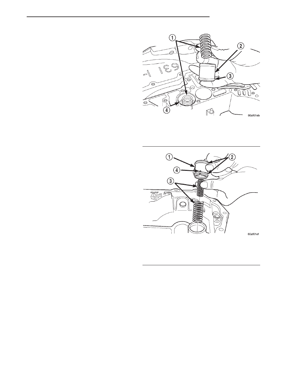
The 41te underdrive, overdrive, low/reverse, and
2/4 clutch hydraulic circuits each contain an accumu-
lator. An accumulator typically consists of a piston,
seals, return spring(s), and a cover or plug. The over-
drive
and
underdrive
accumulators
are
located
within the transaxle case, and are retained by the
valve body (Fig. 6).
The low reverse accumulator (Fig. 7) is also located
within the transaxle case, but the assembly is
retained by a cover and a snap-ring.
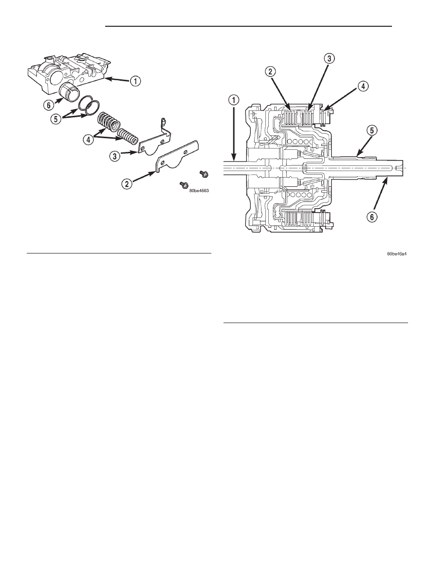
The 2/4 accumulator is located in the valve body. It
is retained by a cover and retaining screws (Fig. 8).
OPERATION
The function of an accumulator is to cushion the
application of a frictional clutch element. When pres-
surized fluid is applied to a clutch circuit, the appli-
cation force is dampened by fluid collecting in the
respective accumulator chamber against the piston
and spring(s). The intended result is a smooth, firm
clutch application.
INPUT CLUTCHES
DESCRIPTION
Three hydraulically applied input clutches are used
to drive planetary components. The underdrive, over-
drive, and reverse clutches are considered input
clutches and are contained within the input clutch
assembly (Fig. 9). The input clutch assembly also
contains:
• Input shaft
• Input hub
• Clutch retainer
• Underdrive piston
Fig. 6 Underdrive and Overdrive Accumulators
1 – RETURN SPRING
2 – UNDERDRIVE CLUTCH ACCUMULATOR
3 – SEAL RING (2)
4 – OVERDRIVE CLUTCH ACCUMULATOR
Fig. 7 Low/Reverse Accumulator Assembly
1 – ACCUMULATOR PISTON
2 – SEAL RINGS
3 – RETURN SPRINGS
4 – (NOTE NOTCH)
JX
TRANSAXLE
21 - 7
DESCRIPTION AND OPERATION (Continued)
• Overdrive/reverse piston
• Overdrive hub
• Underdrive hub
OPERATION
The three input clutches are responsible for driving
different components of the planetary geartrain.
NOTE: Refer to the “Elements In Use” chart in
Diagnosis and Testing for a collective view of which
clutch elements are applied at each position of the
selector lever.
UNDERDRIVE CLUTCH
The underdrive clutch is hydraulically applied in
first, second, and third (direct) gears by pressurized
fluid against the underdrive piston. When the under-
drive clutch is applied, the underdrive hub drives the
rear sun gear.
OVERDRIVE CLUTCH
The overdrive clutch is hydraulically applied in
third (direct) and overdrive gears by pressurized fluid
against the overdrive/reverse piston. When the over-
drive clutch is applied, the overdrive hub drives the
front planet carrier.
REVERSE CLUTCH
The reverse clutch is hydraulically applied in
reverse gear only by pressurized fluid against the
overdrive/reverse piston. When the reverse clutch is
applied, the front sun gear assembly is driven.
HOLDING CLUTCHES
DESCRIPTION
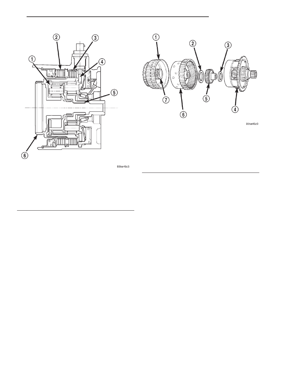
Two hydraulically applied multi-disc clutches are
used to hold planetary geartrain components station-
ary while the input clutches drive others. The 2/4
and Low/Reverse clutches are considered holding
clutches and are contained at the rear of the tran-
saxle case. (Fig. 10).
OPERATION
NOTE: Refer to the “Elements In Use” chart in
Diagnosis and Testing for a collective view of which
clutch elements are applied at each position of the
selector lever.
2/4 CLUTCH
The 2/4 clutch is hydraulically applied in second
and fourth gears by pressurized fluid against the 2/4
clutch piston. When the 2/4 clutch is applied, the
front sun gear assembly is held or grounded to the
transaxle case.
Fig. 8 2/4 Accumulator Assembly
1 – VALVE BODY
2 – RETAINER PLATE
3 – DETENT SPRING
4 – SPRINGS
5 – SEALS
6 – PISTON
Fig. 9 Input Clutch Assembly
1 – INPUT SHAFT
2 – UNDERDRIVE CLUTCH
3 – OVERDRIVE CLUTCH
4 – REVERSE CLUTCH
5 – OVERDRIVE SHAFT
6 – UNDERDRIVE SHAFT
21 - 8
TRANSAXLE
JX
DESCRIPTION AND OPERATION (Continued)
LOW/REVERSE CLUTCH
The Low/Reverse clutch is hydraulically applied in
park, reverse, neutral, and first gears by pressurized
fluid against the Low/Reverse clutch piston. When
the Low/Reverse clutch is applied, the front planet
carrier/rear annulus assembly is held or grounded to
the transaxle case.
PLANETARY GEARTRAIN
DESCRIPTION
The planetary geartrain is located between the
input clutch assembly and the rear of the transaxle
case. The planetary geartrain consists of two sun
gears, two planetary carriers, two annulus (ring)
gears, and one output shaft (Fig. 11).
OPERATION
The planetary geartrain utilizes two planetary gear
sets that connect the transmission input shaft to the
output shaft. Input and holding clutches drive or lock
different planetary members to change output ratio
or direction.
DIFFERENTIAL
DESCRIPTION
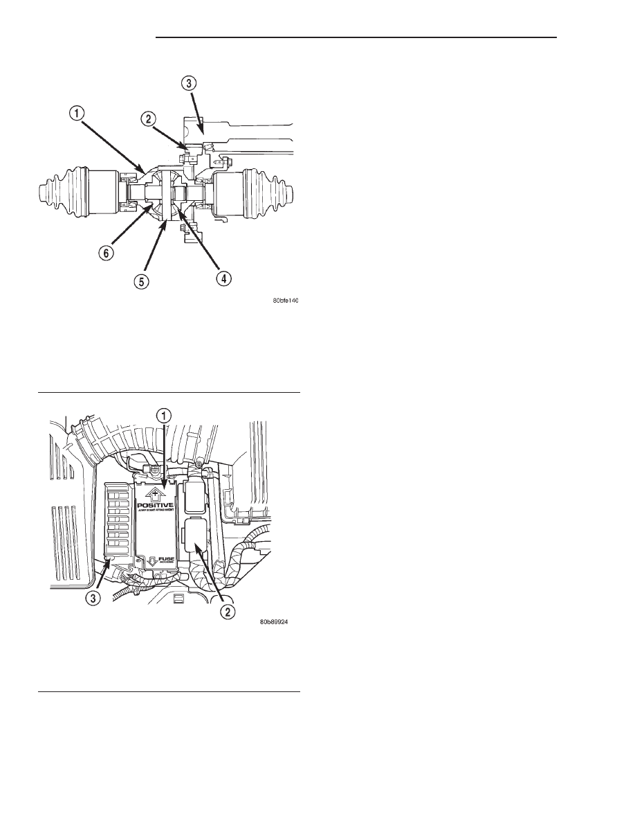
The 41TE differential is a conventional open
design. It consists of a ring gear and a differential
case. The differential case consists of pinion and side
gears, and a pinion shaft. The differential case is
supported in the transaxle by tapered roller bearings
(Fig. 12).
OPERATION
The differential assembly is driven by the transfer
shaft by way of the differential ring gear. The ring
gear drives the differential case, and the case drives
the driveshafts through the differential gears. The
differential pinion and side gears are supported in
the case by thrust washers and a pinion shaft. Dif-
ferential pinion and side gears make it possible for
front tires to rotate at different speeds while corner-
ing.
TRANSMISSION CONTROL MODULE
DESCRIPTION
The Transmission Control Module (TCM) is located
in the engine compartment on the left (driver’s) side
next to the Power Distribution Center (PDC) (Fig.
13).
Fig. 10 2/4 and Low/Reverse Clutches
1 – FRONT PLANET CARRIER/REAR ANNULUS
2 – 2/4 CLUTCH
3 – L/R CLUTCH
4 – REAR PLANET CARRIER/FRONT ANNULUS
5 – REAR SUN GEAR
6 – FRONT SUN GEAR ASSEMBLY
Fig. 11 Planetary Geartrain
1 – FRONT SUN GEAR ASSEMBLY
2 – #6 THRUST BEARING
3 – #7 THRUST BEARING
4 – REAR CARRIER FRONT ANNULUS ASSEMBLY
5 – REAR SUN GEAR
6 – FRONT CARRIER REAR ANNULUS ASSEMBLY
7 – FRONT SUN GEAR
JX
TRANSAXLE
21 - 9
DESCRIPTION AND OPERATION (Continued)
OPERATION
The TCM is the controlling unit for all electronic
operations of the transaxle. The TCM receives infor-
mation regarding vehicle operation from both direct
and indirect inputs, and selects the operational mode
of the transaxle. Direct inputs are hardwired to, and
used specifically by the TCM. Indirect inputs origi-
nate from other components/modules, and are shared
with the TCM via the communication bus.
Some examples of direct inputs to the TCM are:
• Battery (B+) voltage
• Ignition “ON” voltage
• Transmission Control Relay (Switched B+)
• Throttle Position Sensor
• Crankshaft Position Sensor (CKP)
• Transmission Range Sensor (TRS)
• Pressure Switches (L/R, 2/4, OD)
• Transmission Temperature Sensor (Integral to
TRS)
• Input Shaft Speed Sensor
• Output Shaft Speed Sensor
• TRS Hall Effect Switch (Autostick)
Some examples of indirect inputs to the TCM
are:
• Engine/Body Identification
• Manifold Pressure
• Target Idle
• Torque Reduction Confirmation
• Speed Control ON/OFF Switch
• Engine Coolant Temperature
• Ambient/Battery Temperature
• Brake Switch Status
• DRB Communication
Based on the information received from these var-
ious inputs, the TCM determines the appropriate
shift schedule and shift points, depending on the
present operating conditions and driver demand.
This is possible through the control of various direct
and indirect outputs.
Some examples of TCM direct outputs are:
• Transmission Control Relay
• Solenoids (LR/CC, 2/4, OD and UD)
• Vehicle Speed (to PCM)
• Torque Reduction Request (to PCM)
Some examples of TCM indirect outputs are:
• Transmission Temperature (to PCM)
• PRNDL Position (to BCM)
• Autostick Display (to BCM)
In addition to monitoring inputs and controlling
outputs, the TCM has other important responsibili-
ties and functions:
• Storing and maintaining Clutch Volume Indices
(CVI)
• Storing and selecting appropriate Shift Sched-
ules
• System self-diagnostics
• Diagnostic capabilities (with DRB scan tool)
NOTE: If the TCM has been replaced, the “Quick
Learn Procedure” must be performed. Refer to
“Quick Learn Procedure” in Service Procedures of
this group.
Fig. 12 Differential Assembly
1 – DIFFERENTIAL CASE
2 – RING GEAR
3 – TRANSFER SHAFT
4 – PINION GEAR
5 – PINION SHAFT
6 – SIDE GEAR
Fig. 13 Transmission Control Module Location
(Typical)
1 – POWER DISTRIBUTION CENTER (PDC)
2 – POWERTRAIN CONTROL MODULE (PCM)
3 – TRANSMISSION CONTROL MODULE (TCM)
21 - 10
TRANSAXLE
JX
DESCRIPTION AND OPERATION (Continued)
Нет комментариевНе стесняйтесь поделиться с нами вашим ценным мнением.
Текст