
Chrysler Stratus Convertible. Manual — part 30
OXYGEN SENSOR 1/1 UPSTREAM—2.0/2.4L
REMOVAL
(1) Remove the negative battery cable.
(2) Raise and support vehicle.
(3) Disconnect electrical connector from sensor.
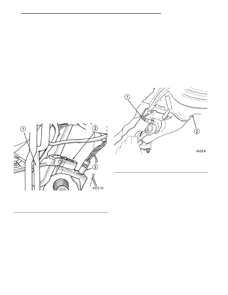
(4) Remove sensor using an oxygen sensor crow
foot wrench such as Snap-On tool YA8875 or equiva-
lent (Fig. 23).
INSTALLATION
(1) After removing the sensor, the exhaust mani-
fold threads must be cleaned with an 18 mm X 1.5 +
6E tap. If reusing the original sensor, coat the sensor
threads with an anti-seize compound such as Loctite
t
771-64 or equivalent. New sensors have compound on
the threads and do not require an additional coating.
Tighten the sensor to 28 N·m (20 ft. lbs.) torque.
(2) Connect electrical connector to sensor.
(3) Lower vehicle.
(4) Install the negative battery cable.
OXYGEN SENSOR 1/2 DOWNSTREAM
The downstream heated oxygen sensor threads into
the exhaust pipe behind the catalytic convertor.
REMOVAL
(1) Remove the negative battery cable.
(2) Raise vehicle.
(3) Disconnect electrical connector from sensor.
(4) Disconnect sensor electrical harness from clips
along body.
(5) Remove sensor using an oxygen sensor crow
foot wrench such as Snap-On tool YA8875 or equiva-
lent (Fig. 24).
INSTALLATION
(1) After removing the sensor, the exhaust mani-
fold threads must be cleaned with an 18 mm X 1.5 +
6E tap. If reusing the original sensor, coat the sensor
threads with an anti-seize compound such as Loctite
t
771-64 or equivalent. New sensors have compound on
the threads and do not require an additional coating.
Tighten the sensor to 28 N·m (20 ft. lbs.) torque.
(2) Connect sensor electrical harness to clips along
body.
(3) Connect electrical connector to sensor.
(4) Lower vehicle.
(5) Install the negative battery cable.
AIR INLET RESONATOR
2.0L
REMOVAL
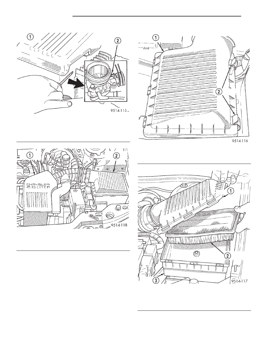
(1) Loosen screw holding resonator to throttle body
(Fig. 25).
(2) Loosen clamp holding resonator to air inlet
tube. Remove resonator.
INSTALLATION
(1) Install air inlet resonator to throttle body.
(2) Install air inlet tube to resonator.
(3) Tighten clamps to 3
6.5 N·m (2565 in. lbs.)
torque.
AIR CLEANER
The air cleaner housing attaches to the inner
fender in front of the driver’s side strut tower (Fig.
26). An ambient air duct supplies underhood air for
the engine.
Fig. 23 Oxygen Sensor 1/1 Upstream
1 – EXHAUST PIPE FLANGE
2 – CROW FOOT WRENCH
3 – UPSTREAM OXYGEN SENSOR
Fig. 24 Oxygen Sensor 1/2 Downstream
1 – DOWNSTREAM HEATED OXYGEN SENSOR
2 – CATALYTIC CONVERTOR
JX
FUEL SYSTEM
14 - 37
REMOVAL AND INSTALLATION (Continued)
FILTER ELEMENT REPLACEMENT
REMOVAL
(1) Unfasten clasps on rear of air cleaner housing
cover. Lift cover off air cleaner housing (Fig. 27).
(2) Remove filter element (Fig. 28).
(3) If necessary, clean the inside of the air cleaner
housing.
INSTALLATION
(1) Install new filter element.
(2) Place cover over air cleaner housing. Snap
clasps in place.
Fig. 25 Air Inlet Resonator Attachment to Throttle
Body
1 – AIR INLET RESONATOR
2 – RESONATOR CLAMP SCREW
Fig. 26 Air Inlet System
1 – AIR INLET RESONATOR
2 – AIR CLEANER HOUSING
Fig. 27 Air Cleaner Cover Clasps
1 – AIR CLEANER HOUSING COVER
2 – CLASPS
Fig. 28 Air Cleaner Housing and Element
1 – HOUSING COVER
2 – AIR CLEANER ELEMENT
3 – HOUSING
14 - 38
FUEL SYSTEM
JX
REMOVAL AND INSTALLATION (Continued)
ENGINE COOLANT TEMPERATURE SENSOR
2.0L
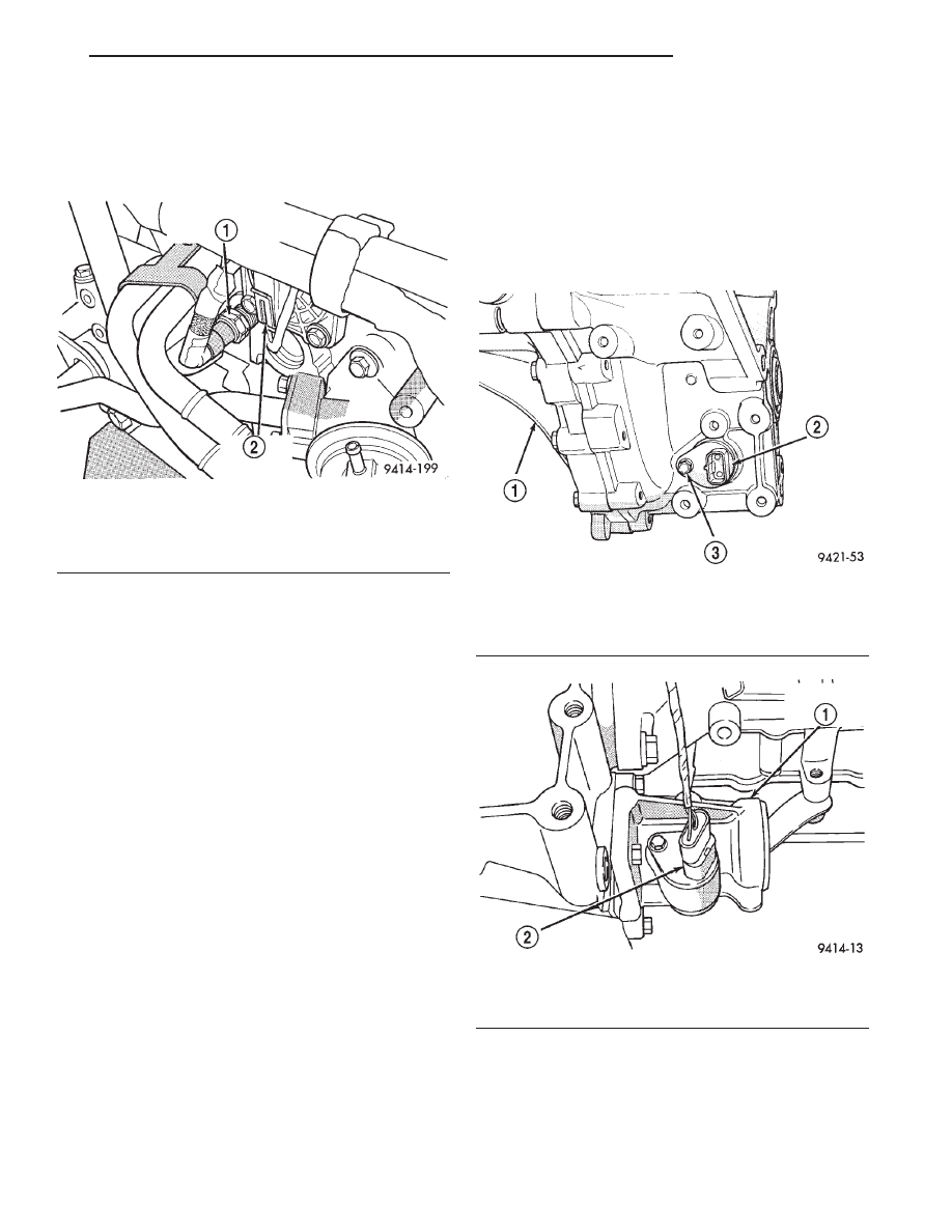
The engine coolant temperature sensor threads
into the rear of the cylinder head (Fig. 29).
REMOVAL
(1) Remove the negative battery cable.
(2) With the engine cold, drain coolant until level
drops below sensor level. Refer to the Cooling System
section.
(3) Disconnect coolant sensor electrical connector.
(4) Remove coolant sensor.
INSTALLATION
(1) Install coolant sensor. Tighten sensor to: 19
6 2
N·m (14
6 2 ft. lbs.) torque.
(2) Attach electrical connector to sensor.
(3) Fill cooling system. Refer to the Cooling Sys-
tem section.
(4) Install the negative battery cable.
VEHICLE SPEED SENSOR
The vehicle speed sensor is located in the transmis-
sion extension housing (Fig. 30) or (Fig. 31).
REMOVAL
(1) Remove the negative battery cable.
(2) Raise and support vehicle.
(3) Disconnect electrical connector from sensor.
(4) Remove the sensor mounting bolt.
(5) Lift the sensor out of the transaxle extension
housing. Ensure the O-ring was removed with the
sensor.
INSTALLATION
The speed sensor gear meshes with a gear on the
output shaft.
(1) With O-ring in place, install sensor.
(2) Install mounting bolt and tighten to 7 N·m (60
in.lbs.).
(3) Connect electrical connector to sensor.
(4) Lower vehicle.
(5) Install the negative battery cable.
Fig. 29 Engine Coolant Temperature Sensor—2.0L
Engine
1 – ENGINE COOLANT TEMPERATURE SENSOR
2 – CAMSHAFT POSITION SENSOR
Fig. 30 Vehicle Speed Sensor Manual
1 – TRANSAXLE
2 – SPEED SENSOR
3 – SPEED SENSOR RETAINING BOLT
Fig. 31 Vehicle Speed Sensor Automatic
1 – TRANSAXLE EXTENSION HOUSING
2 – VEHICLE SPEED SENSOR
JX
FUEL SYSTEM
14 - 39
REMOVAL AND INSTALLATION (Continued)
SPECIFICATIONS
VEHICLE EMISSION CONTROL INFORMATION
LABEL
DESCRIPTION
All models have a Vehicle Emission Control Infor-
mation (VECI) Label. Chrysler permanently attaches
the label in the engine compartment. It cannot be
removed without defacing information and destroying
the label.
The label contains the vehicle’s emission specifica-
tions and vacuum hose routings. All hoses must be
connected and routed according to the label.
TORQUE
DESCRIPTION
TORQUE
Camshaft Position Semsor . . . 12 N·m (105 in. lbs.)
Crankshaft Position Sensor . . 12 N·m (105 in. lbs.)
Engine Coolant Temperature Sensor . . . . . . 28 N·m
(20 ft. lbs.)
IAC Motor-To-Throttle Body Bolts . . . . . . . . 3 N·m
(25 in. lbs.)
MAP Sensor Mounting Screws . . 3 N·m (25 in. lbs.)
Oxygen Sensor . . . . . . . . . . . . . 28 N·m (20 ft. lbs.)
Powertrain Control Module (PCM) Mounting
Screws . . . . . . . . . . . . . . . . . . 4 N·m (35 in. lbs.)
Throttle Body Mounting Bolts . . 26 N·m (19 ft. lbs.)
Throttle Position Sensor . . . . . . . 3 N·m (25 in. lbs.)
Throttle Shield Bolt . . . . . . . . . 4.5 N·m (40 in. lbs.)
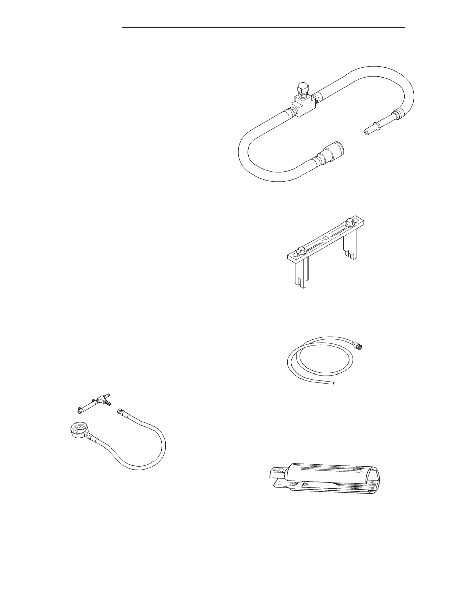
SPECIAL TOOLS
FUEL
Pressure Gauge Assembly C–4799–B
Fuel Pressure Test Adapter 6539
Spanner Wrench 6856
Fuel Line Adapter 1/4
O2S (Oxygen Sensor) Remover/Installer—C-4907
14 - 40
FUEL SYSTEM
JX
Нет комментариевНе стесняйтесь поделиться с нами вашим ценным мнением.
Текст