
Chrysler Stratus Convertible. Manual — part 157
(3) Remove right instrument panel side trim.
(4) Remove two screws at lower right side support
beam.
(5) Remove bolt for instrument panel support at
A-pillar.
(6) Remove left instrument panel side trim.
(7) Remove upper instrument panel bezel.
(8) Remove lower knee bolster.
(9) Remove console screws at instrument panel.
(10) Remove gearshift knob.
(11) Remove shifter bezel.
(12) Remove console screws at rear. Remove rear
half of console.
(13) Remove front console screws. Remove front
half of console.
(14) Remove right side instrument panel support
strut.
(15) Drain coolant.
(16) Remove heater hoses at cowl.
(17) Remove heater core cover screws and cover.
(18) Remove heater core.
INSTALLATION
(1) Carefully install new heater core into the
heater housing.
(2) Fasten heater core cover to housing with
screws provided.
(3) Reinstall all necessary trim.
(4) Fill coolant to level.
(5) Reconnect battery.
HEATER HOSES
The heater hoses attach at the engine compart-
ment cowl onto the heater core inlet/outlet and on
the left side of the engine.
HEATER HOSES (2.0L-2.4L)
The heater hoses are serviced separately of each
other. The hoses can not be serviced with bulk roll
heater hose. If it is necessary to replace a hose, use
hose of the exact diameter and size and shape. The
hoses are attached using spring tension clamps.
REMOVAL
NOTE: Review Safety Precautions and Warnings
before proceeding with this operation.
(1) Drain engine cooling system. Refer to Group 7,
Cooling System.
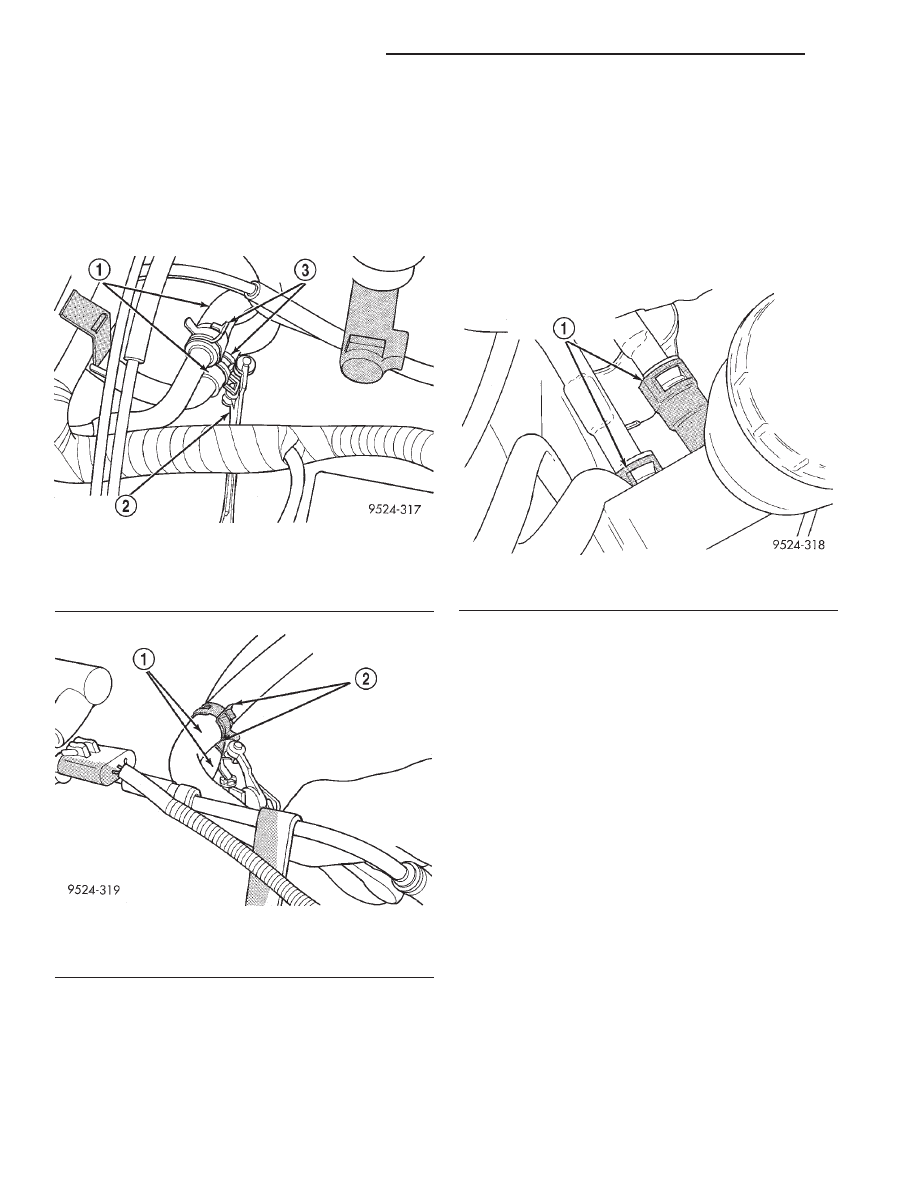
(2) Using spring tension clamp pliers, remove
clamps at each end of hose to be removed (Fig. 53)
and (Fig. 54).
(3) Carefully rotate hose back and forth while tug-
ging slightly away from connector nipple.
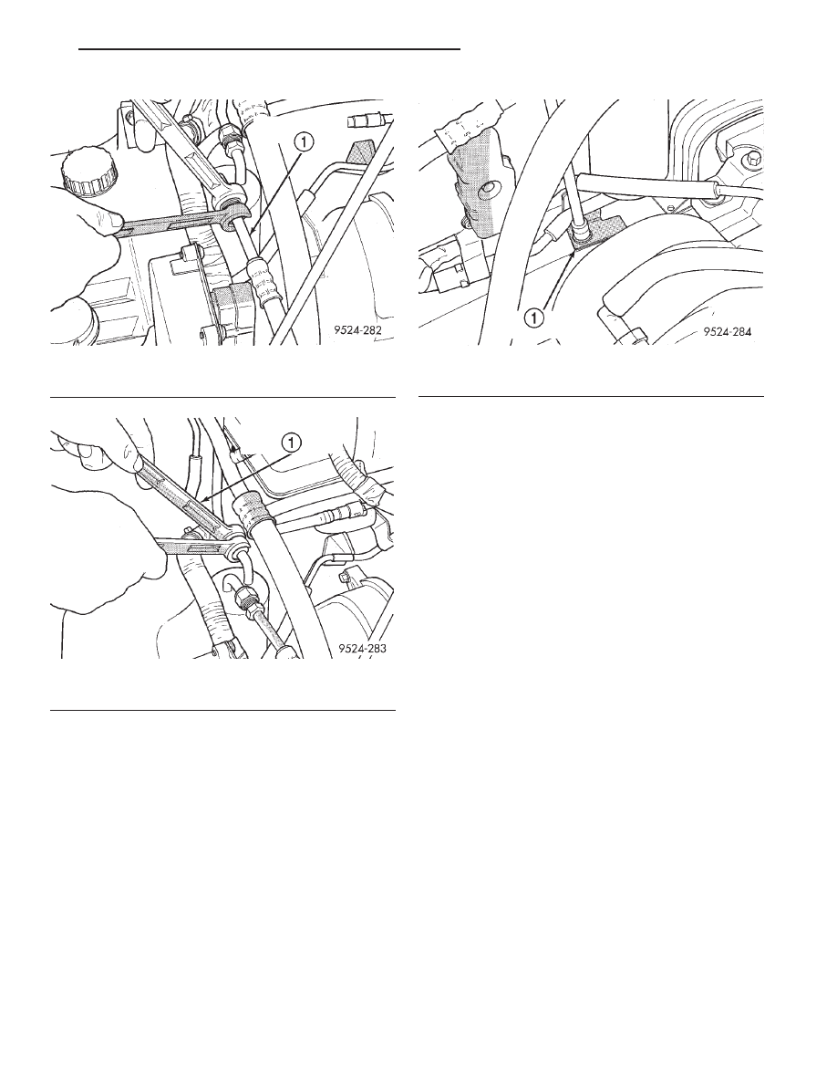
Fig. 50 Liquid Line From Condenser
1 – LIQUID LINE TO CONDENSER
Fig. 51 Liquid Line From Expansion Valve
1 – LIQUID LINE TO EXPANSION VALVE
Fig. 52 Receiver/Drier Bracket
1 – RECEIVER/DRIER BRACKET
JX
HEATING AND AIR CONDITIONING
24 - 25
REMOVAL AND INSTALLATION (Continued)
CAUTION: When removing hoses from heater core
inlet or outlet nipples, do not use excessive force.
Heater core may become damaged and leak engine
coolant into heater unit.
INSTALLATION
For installation, reverse the above procedures.
HEATER HOSES (2.5L)
REMOVAL
The heater hoses for the 2.5L engine are preformed
hoses with quick connect fittings at the engine. These
hoses are not serviceable and must be replaced using
OEM parts. The hoses are attached at the heater
core using spring tension clamps.
NOTE: Review Safety Precautions and Warnings
before proceeding with this operation.
(1) Drain engine cooling system. Refer to Group 7,
Engine Cooling.
(2) Using thin slide-jaw pliers, pinch quick connect
fitting in, of hose to be removed (Fig. 55).
(3) Remove intake manifold plenum. Refer to
Group 11, Exhaust System And Intake Manifold for
service information.
(4) Using spring tension clamp pliers, remove
clamp at heater core end of hose to be removed
(Fig. 54).
(5) Carefully rotate hose back and forth while tug-
ging slightly away from connector nipple.
CAUTION: When removing hoses from heater core
inlet or outlet nipples, do not use excessive force.
Heater core may become damaged and leak engine
coolant into heater unit.
INSTALLATION
For installation, reverse the above procedures.
LIQUID LINE
TO EXPANSION VALVE
REMOVAL
(1) Remove refrigerant from the A/C system using
a refrigerant recovery machine.
(2) Remove A/C quick connect clip at expansion
valve (Fig. 56).
Fig. 53 Heater Hose Connection At Engine
1 – HEATER HOSES
2 – SPRING TENSION CLAMP PLIERS
3 – HEATER HOSE CLAMPS
Fig. 54 Heater Hose Connection At Heater Core
1 – HEATER HOSES
2 – HEATER HOSE SPRING TENSION CLAMPS
Fig. 55 Heater Hose Connection At Engine
1 – HEATER HOSE QUICK CONNECT FITTINGS
24 - 26
HEATING AND AIR CONDITIONING
JX
REMOVAL AND INSTALLATION (Continued)
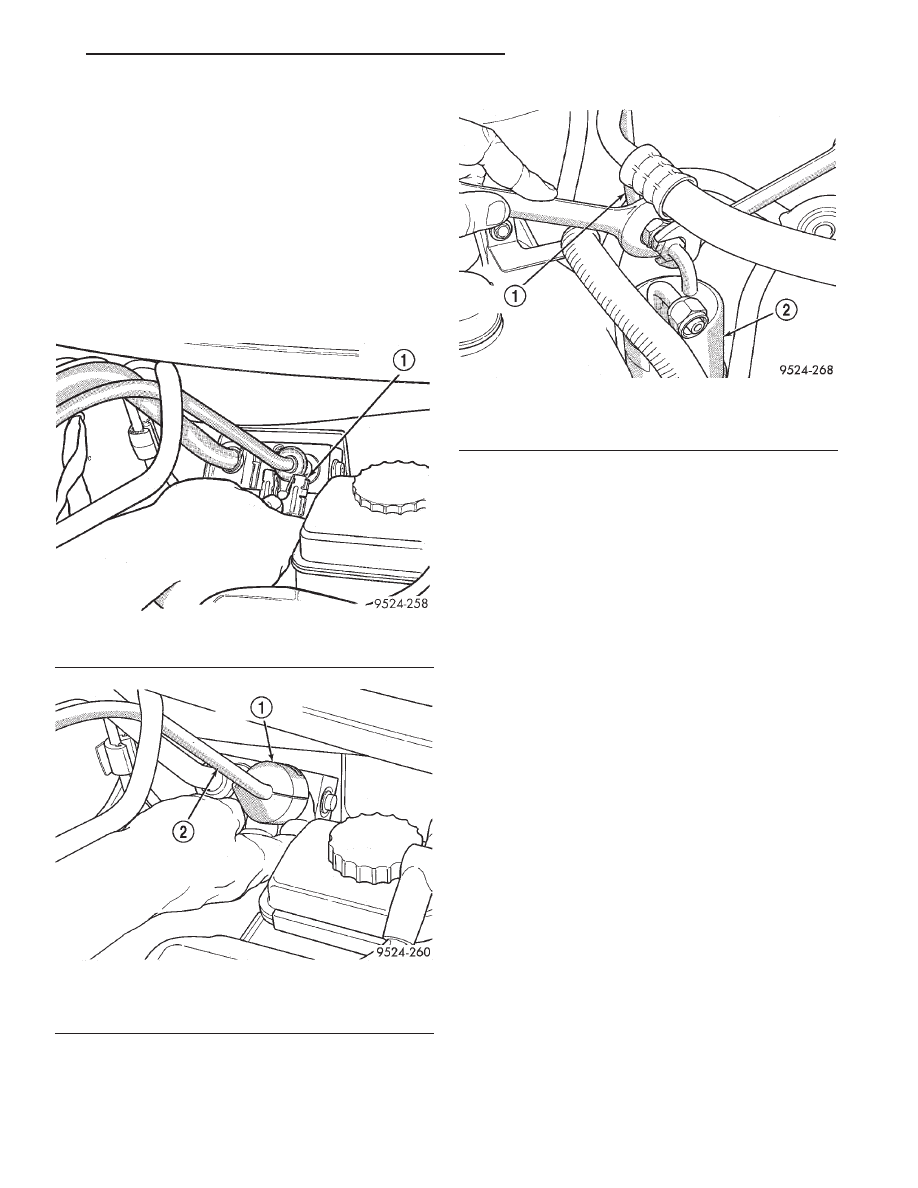
(3) Disconnect quick connector on expansion valve.
Remove liquid line from expansion valve. Use Special
Tool kit 7193 to disconnect quick connector (Fig. 57).
CAUTION: Cap all lines that are not being replaced
and cap the expansion valve tubes.
(4) Disconnect liquid line from the receiver/drier
(Fig. 58).
(5) Remove the liquid line from the vehicle.
INSTALLATION
For installation, reverse the above procedures.
TO CONDENSER
REMOVAL
(1) Remove refrigerant from the A/C system using
a refrigerant recovery machine.
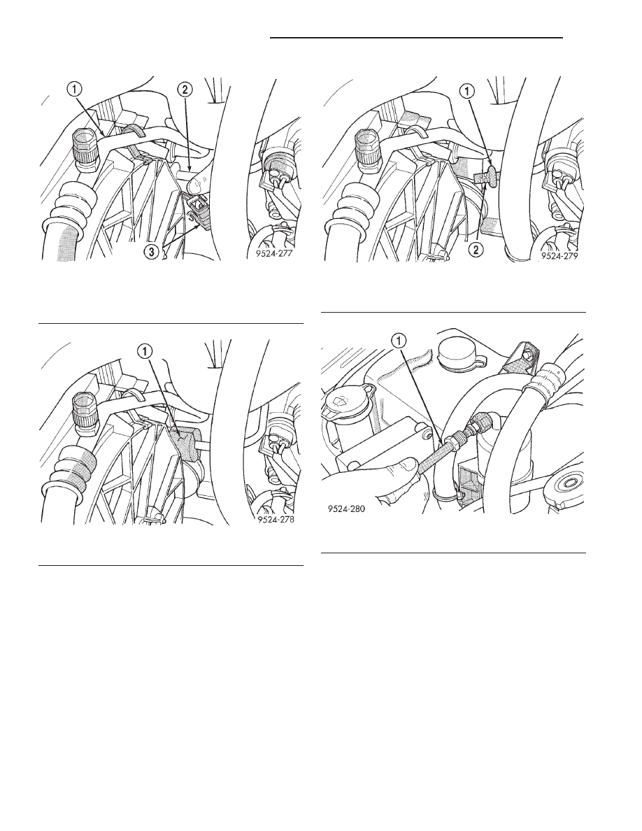
(2) Remove A/C quick connect clip at condenser
(Fig. 59).
(3) Disconnect
quick
connector
at
condenser.
Remove liquid line from condenser. Use special tool
kit 7193 to disconnect quick connector (Fig. 60).
Remove line at condenser (Fig. 61).
CAUTION: Cap all lines that are not being replaced
and cap the condenser inlet.
(4) Disconnect liquid line from the receiver/drier
(Fig. 62).
(5) Remove the liquid line from the vehicle.
INSTALLATION
For installation, reverse the above procedures.
MODE DOOR ACTUATOR MOTOR
NOTE: If battery voltage is low or not sensed at the
actuator/motor for less than a (60) second interval,
the
actuator/motor
will
be
out
of
calibration.
Remove the M1 (I. O. D.) fuse for a minimum of (60)
seconds. The actuator/motor will then self calibrate
itself upon reinstallation of fuse.
Fig. 56 Liquid Line Clip At Expansion Valve
1 – LIQUID LINE CLIP
Fig. 57 Use Special Tool 7240 For Quick Connect
1 – SPECIAL TOOL OTC 7240
2 – LIQUID LINE
Fig. 58 Liquid Line At Receiver/Drier
1 – LIQUID LINE AT RECEIVER DRIER
2 – RECEIVER DRIER
JX
HEATING AND AIR CONDITIONING
24 - 27
REMOVAL AND INSTALLATION (Continued)
The mode door actuator is an electric motor. It
mechanically positions the A/C unit panel/bi-level
door and the floor/defrost door. Prior to part replace-
ment, re-calibration of the HVAC actuator is recom-
mended. Calibration is performed by disconnecting
the battery negative cable or the removal of the
instrument panel M-1 fuse. Electrical power should
be re-established after (60) seconds which will auto-
matically initiate the software calibration procedure.
If this procedure fails, it will be necessary to replace
the mode door actuator/motor. The mode door actua-
tor/motor is not serviceable and must be replaced if
found to be defective.
The mode door actuator is located on the upper left
side of the A/C- Heater housing (Fig. 63).
REMOVAL
(1) Disconnect battery negative cable.
(2) Remove left underpanel silencer/duct.
(3) Remove
electrical
connection
on
actuator
(Fig. 64).
(4) Remove actuator retaining screws. Then pull
actuator straight down. Upon removal, note the shaft
position of the actuator, because the shaft on this
motor is keyed. When installing new actuator, its
shaft must be positioned in the same location.
INSTALLATION
For installation, reverse the above procedures.
RECIRCULATION DOOR CABLE
The RECIRC door is actuated by a cable which
mechanically positions the door.
Fig. 59 Clip Removal
1 – DISCHARGE LINE
2 – LIQUID LINE
3 – LIQUID LINE CLIP
Fig. 60 Quick Coupler Using Special Tool 7240
1 – SPECIAL TOOL OTC 7240
Fig. 61 Line At Condenser
1 – LIQUID LINE
2 – DOUBLE O-RINGS
Fig. 62 Liquid Line at Receiver/Drier
1 – LIQUID LINE AT RECEIVER-DRIER
24 - 28
HEATING AND AIR CONDITIONING
JX
REMOVAL AND INSTALLATION (Continued)
Нет комментариевНе стесняйтесь поделиться с нами вашим ценным мнением.
Текст