
Chrysler Stratus Convertible. Manual — part 155
INSTALLATION
(1) Position the back of the field coil on the com-
pressor front cover. Be sure the locating nipple on the
back of the coil lines up with the locating indentation
on the front cover. This ensures correct position of
the coil and lead wire.
(2) Fasten lead wire to the compressor front cover
with the retaining clip. Connect the lead wire to the
thermal limiter switch.
(3) Install field coil retaining snap ring (bevel side
outward) with snap ring pliers. Insure snap ring is
properly seated into groove.
CAUTION: If snap rings on field coil or pulley
assembly are not fully seated, they will vibrate out.
A clutch failure and possible severe damage to the
compressor could result.
(4) Position pulley assembly onto compressor.
CAUTION: Do not mar the pulley frictional surface.
(5) Install pulley assembly retaining snap ring
(bevel side outward) with snap ring pliers. Insure
snap ring is properly seated into groove.
(6) Place a trial stack of shims, 2.54 mm (0.10 in.)
thick, on the compressor shaft.
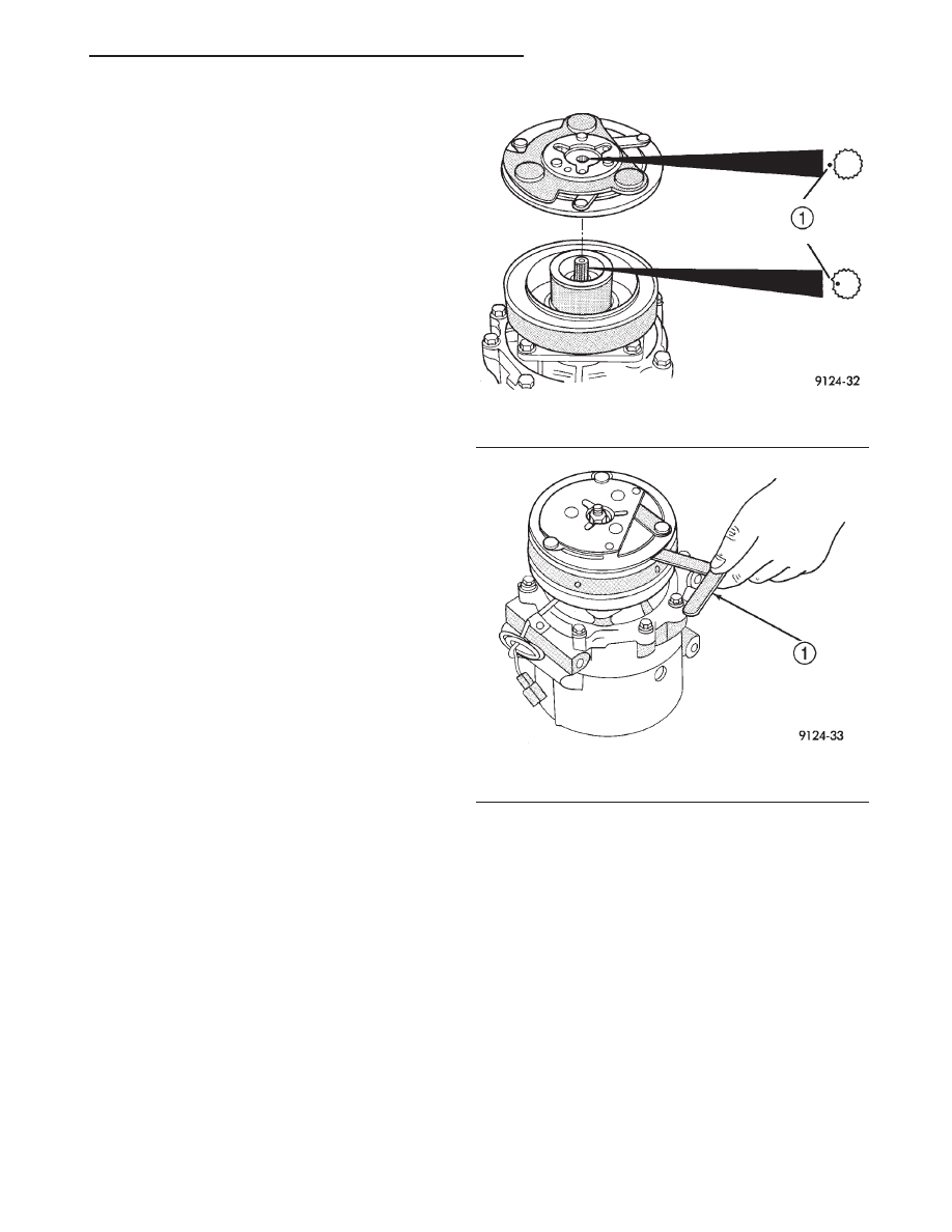
(7) Install clutch plate on compressor shaft. Note
the machined mating splines (Fig. 20).
(8) With the front clutch plate assembly tight
against the shims, measure the air gap between
clutch plate and pulley face with feeler gauges (Fig.
21). The air gap should be between 0.35 and 0.65 mm
(0.013 and 0.025 inch). If proper air gap is not
obtained, add or subtract shims until desired air gap
is obtained.
(9) Install compressor shaft nut. Tighten nut to
17.6 N·m (13 ft. lbs.) torque.
(10) Shims may compress after tightening shaft
bolt. Check air gap in four or more places to verify if
air gap is still correct. Spin pulley for final check.
(11) Install the compressor onto the mount.
CLUTCH BREAK-IN
After installing a new field coil-core, check for cor-
rect voltage/amperage. Cycle the A/C clutch approxi-
mately 20 times (5 seconds on and 5 seconds off). For
this procedure run engine at 1,500 to 2,000 rpm and
set the system to MAX A/C mode. This procedure will
seat the opposing friction surfaces and provide a
higher clutch torque capability.
CONDENSER
The condenser is located between the radiator and
the front bumper. The condenser can be serviced
without having to drain the cooling system or remove
the radiator.
WARNING: AVOID BREATHING A/C REFRIGERANT
AND LUBRICANT VAPOR OR MIST. EXPOSURE MAY
IRRITATE EYES, NOSE AND THROAT. USE ONLY
APPROVED SERVICE EQUIPMENT MEETING SAE
REQUIREMENTS TO RECOVER R-134a SYSTEM. IF
ACCIDENTAL SYSTEM DISCHARGE OCCURS, VEN-
TILATE WORK AREA BEFORE RESUMING SER-
VICE.
R-134a SERVICE EQUIPMENT OR VEHICLE A/C
SYSTEM SHOULD NOT BE PRESSURE TESTED OR
LEAK TESTED WITH COMPRESSED AIR. SOME
MIXTURES OF AIR/R-134a HAVE BEEN SHOWN TO
BE COMBUSTIBLE AT ELEVATED PRESSURES.
THESE MIXTURES ARE POTENTIALLY DANGER-
OUS AND MAY RESULT IN FIRE OR EXPLOSION
CAUSING INJURY OR PROPERTY DAMAGE.
Fig. 20 Aligning Clutch Plate Splines
1 – MATING MARK: WHERE THERE IS NO SPLINE
Fig. 21 Measuring Air Gap
1 – FEELER GAUGE
JX
HEATING AND AIR CONDITIONING
24 - 17
REMOVAL AND INSTALLATION (Continued)
REMOVAL
(1) Remove refrigerant from the A/C system using
a refrigerant recovery machine.
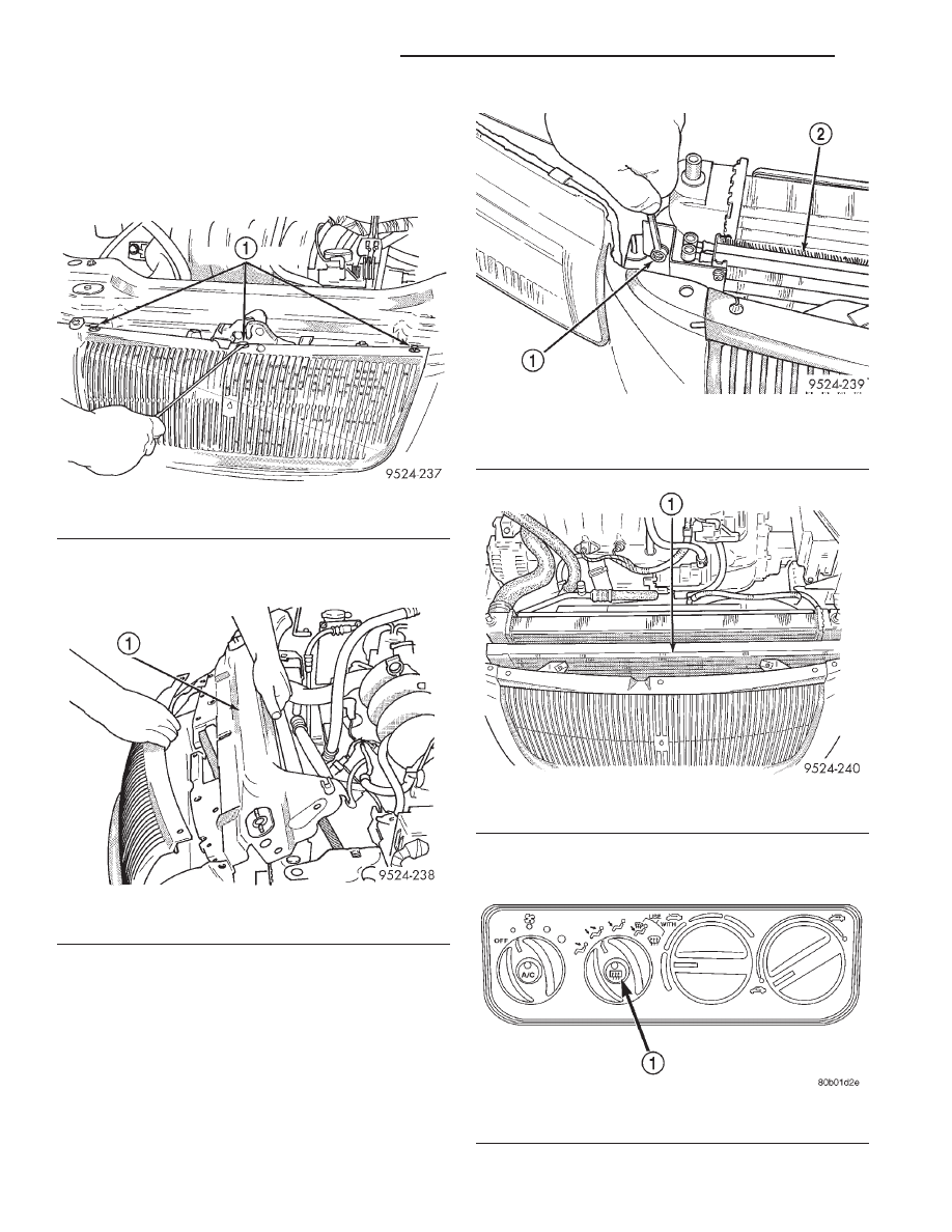
(2) Remove grille retainers (Fig. 22). Refer to
Group 23, Body for removal procedures.
(3) Remove upper radiator support crossmember
(Fig. 23).
(4) Disconnect and cap A/C lines at the condenser.
(5) Remove condenser line support bracket.
(6) Remove condenser mounting bolts (Fig. 24).
CAUTION: Avoid bending or breaking condenser
inlet tube when lifting condenser from the vehicle.
(7) Lift condenser from vehicle (Fig. 25).
INSTALLATION
For installation, reverse above procedures.
CONTROL MODULE
The control module is located below the radio.
Fig. 22 Grille Retainers
1 – GRILLE RETAINERS
Fig. 23 Radiator Support Crossmember
1 – UPPER RADIATOR CROSSMEMBER
Fig. 24 Condenser Mounting
1 – CONDENSER MOUNTING
2 – CONDENSER
Fig. 25 Condenser Removal
1 – CONDENSER
Fig. 26 HVAC Control Module
1 – REAR WINDOW DEFOGGER SWITCH
24 - 18
HEATING AND AIR CONDITIONING
JX
REMOVAL AND INSTALLATION (Continued)
REMOVAL
(1) Place the ignition key in the OFF position
before removing control module.
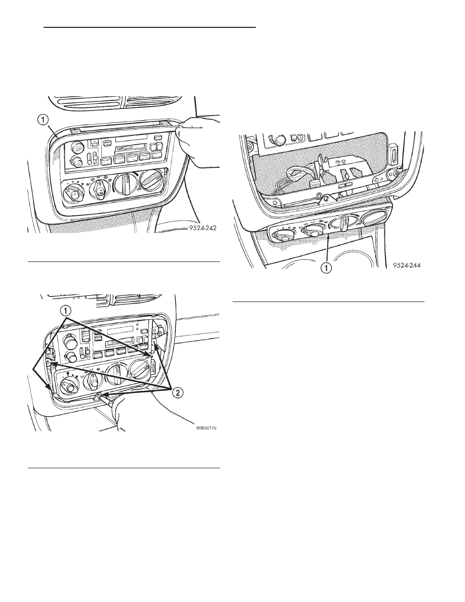
(2) Remove trim bezel (Fig. 27).
(3) Remove cluster hood bezel retaining screws in
the trim bezel opening (Fig. 28).
(4) Pry up the cluster hood bezel a few inches to
expose the cubby bin/cigar lighter bezel screws.
(5) Remove the cubby bin/cigar lighter bezel and
wiring.
(6) Remove the control module retaining screws.
(7) Drop the A/C control module into the cigar
lighter/cubby bin bezel opening (Fig. 29). Then dis-
connect the wiring on the rear of the control module.
(8) Release the cable clips from the top of the con-
trol module. Retain the clips for future use. Then dis-
connect the temperature control and recirculation
control cables.
(9) Remove the control module.
INSTALLATION
For installation, reverse the above procedures. Ver-
ify that the cables are properly adjusted and the
module is seated properly.
CABLE ADJUSTMENT
The cables must be adjusted for proper function of
the control module. To adjust the cable, attach the
cable to the lever arm of the control module. Turn
the knob fully counterclockwise. Pull the cable jacket
away from the cable end until taut. Clip the cable
jacket to the control module. The knob should travel
a full 180° if the cable is properly adjusted.
Fig. 27 Control Module
1 – TRIM BEZEL
Fig. 28 Control Module Screws
1 – CONTROL MODULE SCREWS
2 – CLUSTER HOOD SCREWS
Fig. 29 Control Module At Bezel Opening
1 – CONTROL MODULE
JX
HEATING AND AIR CONDITIONING
24 - 19
REMOVAL AND INSTALLATION (Continued)
DISCHARGE LINE
REMOVAL
(1) Remove refrigerant from the A/C system using
a refrigerant recovery machine.
(2) Disconnect A/C pressure transducer wire har-
ness.
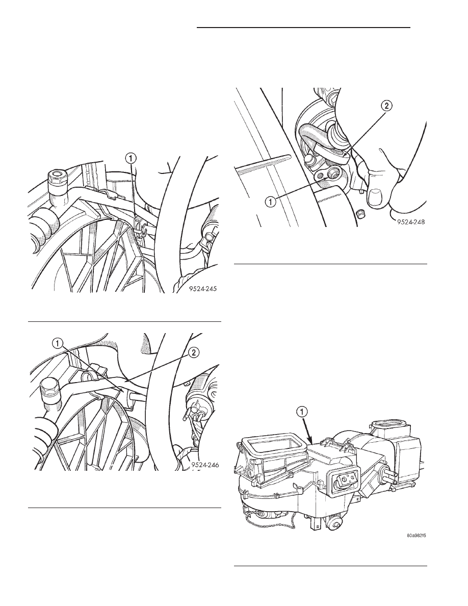
(3) Remove quick connect clip and disconnect quick
connect at condenser using Special Tool kit 7193 (Fig.
30) and (Fig. 31).
CAUTION: Cap all lines that are not being replaced
and cap the expansion valve tubes.
(4) Disconnect line at A/C compressor (Fig. 32).
Remove discharge line.
INSTALLATION
For installation, reverse the above procedures.
Tighten bolts to 22 N·m (200 in. lbs.).
EVAPORATOR
The Heater A/C housing must be removed from the
vehicle when replacing the evaporator.
REMOVAL
(1) Disconnect battery negative remote cable.
CAUTION: The refrigerant must be removed from
the system before removing Heater-A/C housing.
Use a refrigerant recovery machine.
(2) Remove A/C housing from vehicle (Fig. 33).
Refer to Heater-A/C Housing Removal and Installa-
tion in this section for procedure.
Fig. 30 Quick Connect Clip
1 – DISCHARGE LINE CLIP
Fig. 31 Special Tool For Line At Condenser
1 – SPECIAL TOOL OTC 7241
2 – DISCHARGE LINE
Fig. 32 Line at Compressor
1 – DISCHARGE PORT
2 – DISCHARGE LINE
Fig. 33 A/C Housing
1 – HVAC MODULE
24 - 20
HEATING AND AIR CONDITIONING
JX
REMOVAL AND INSTALLATION (Continued)
Нет комментариевНе стесняйтесь поделиться с нами вашим ценным мнением.
Текст