
Chrysler Stratus Convertible. Manual — part 61
KNUCKLE (REAR)
REMOVAL
(1) Raise vehicle on jackstands or centered on a
frame contact type hoist. See Hoisting in the Lubri-
cation and Maintenance section of this manual, for
the required lifting procedure to be used for this
vehicle.
(2) Remove the rear wheel and tire assembly from
the vehicle.
(3) Remove rear brake drum from rear hub and
bearing assembly.
(4) If vehicle is equipped with antilock brakes
remove the rear wheel speed sensor from the brake
support plate and brake flex hose routing bracket
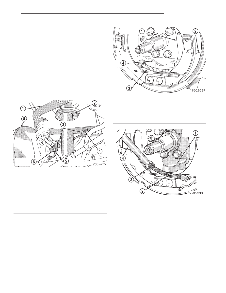
(Fig. 7).
(5) Remove the park brake cable from the park
brake actuating lever (Fig. 8). Then remove the park
brake cable from the rear brake support plate (Fig.
9). Park brake cable is removed from brake support
plate using this procedure. Position a 1/2 inch box
end wrench over cable retainer (Fig. 9) to collapse
retaining tabs. Then pull bear brake cable from
brake support plate.
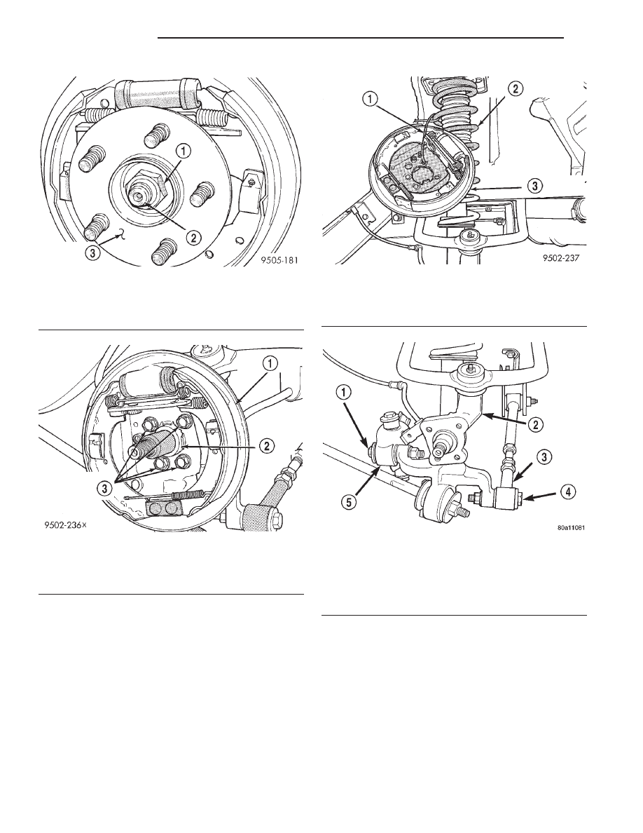
(6) Remove the rear hub/bearing assembly retain-
ing nut (Fig. 10). Then remove the washer and the
hub/bearing assembly from the knuckle.
(7) Remove the 4 bolts (Fig. 11) attaching rear
brake support plate to knuckle. Then remove brake
support plate, brake shoes and wheel cylinder as an
assembly from rear knuckle. It is not necessary to
remove brake flex hose from wheel cylinder
when removing support plate. Brake support
plate when removed, must be supported using
mechanics wire as shown in (Fig. 12).
(8) Remove the nuts and bolts attaching the for-
ward and rear lateral links (Fig. 13) to the rear
knuckle.
Fig. 7 Rear Wheel Speed Cable Routing And
Attachment
1 – UPPER CONTROL ARM
2 – SHOCK ABSORBER
3 – SPEED SENSOR CABLE ROUTING CLIPS
4 – BOLT
5 – SPEED SENSOR CABLE
6 – BRAKE FLEX HOSE BRACKET
7 – BOLT
8 – BRAKE DRUM
Fig. 8 Park Brake Cable Attachment To Actuating
Lever
1 – PARK BRAKE ACTUATING LEVER
2 – TRAILING BRAKE SHOE
3 – PARK BRAKE CABLE
4 – BRAKE SUPPORT PLATE
Fig. 9 Park Brake Cable Removal From Brake
Support Plate
1 – REAR BRAKE SUPPORT PLATE
2 – PARK BRAKE CABLE
3 – PARK BRAKE CABLE RETAINER
4 – 1/2” BOX END WRENCH
JX
SUSPENSION
2 - 53
REMOVAL AND INSTALLATION (Continued)
(9) Remove cotter pin and castle nut attaching
upper control arm ball joint to knuckle.
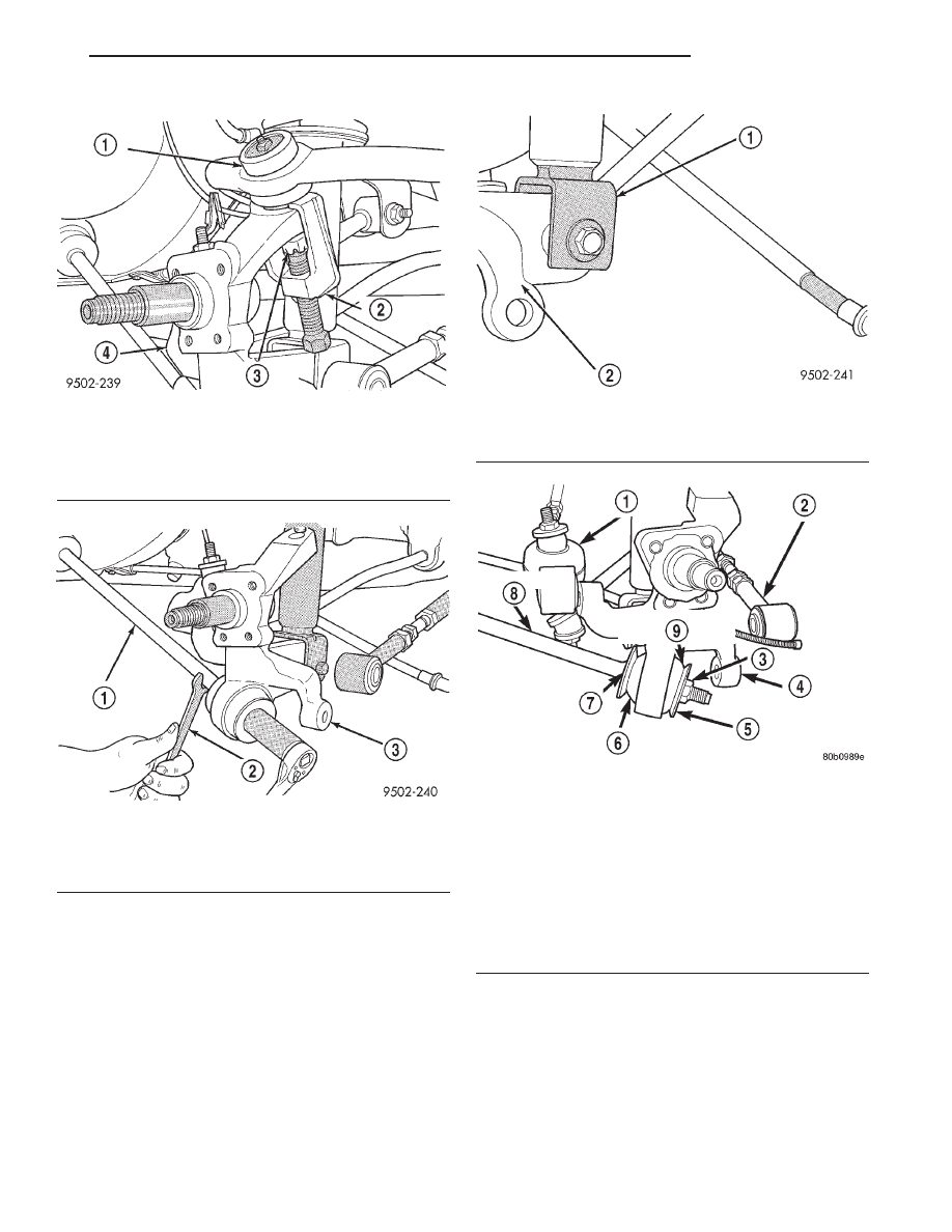
(10) Remove ball joint stud from knuckle using
Puller, Special Tool, CT-1106 (Fig. 14). When using
puller, install castle nut on ball joint stud (Fig. 14) to
protect threads from damage.
(11) Remove the nut and washer attaching the
trailing link to the rear knuckle. Use a wrench on
the flat of the trailing link to keep it from turning
when removing nut (Fig. 15).
(12) Remove the shock absorber clevis bracket to
knuckle attaching nut and bolt (Fig. 16).
(13) Remove the knuckle assembly from the vehi-
cle.
INSTALLATION
(1) Install knuckle on clevis bracket of rear shock
absorber.
Then
install
clevis
bracket
to
shock
absorber attaching bolt with head of bolt facing rear
of vehicle (Fig. 16).
CAUTION: When
installing
trailing
link
bushing
retainers, retainers must be installed with cupped
side of retainer facing away from bushing and
knuckle (Fig. 17).
(2) Install knuckle on trailing link. Install the
trailing link outer bushing, gold bushing retainer and
Fig. 10 Hub/Bearing Assembly Retaining Nut
1 – RETAINING NUT
2 – SPINDLE
3 – HUB/BEARING ASSEMBLY
Fig. 11 Rear Brake Support Plate Mounting Bolts
1 – REAR BRAKE SUPPORT PLATE
2 – REAR KNUCKLE
3 – BRAKE SUPPORT PLATE ATTACHING BOLTS
Fig. 12 Correctly Stored Rear Brake Support Plate
1 – WIRE HANGER
2 – REAR SHOCK ABSORBER ASSEMBLY
3 – REAR BRAKE SUPPORT PLATE
Fig. 13 Lateral Link Attachment To Rear Knuckle
1 – BOLT
2 – KNUCKLE
3 – REAR LATERAL LINK
4 – BOLT
5 – FORWARD LATERAL LINK
2 - 54
SUSPENSION
JX
REMOVAL AND INSTALLATION (Continued)
retaining nut on trailing link (Fig. 17). Using a large
adjustable wrench, to keep trailing link from rotating
securely tighten the trailing link retaining nut (Fig.
17) to a torque of 99 N·m (73 ft. lbs.).
(3) Install the upper ball joint stud in the knuckle.
Install and tighten the ball joint stud castle nut to a
torque of 85 N·m (63 ft. lbs.). Install cotter pin in ball
joint stud.
(4) Install the front and rear lateral links and
attaching nuts and bolts on the knuckle (Fig. 13)
Tighten the lateral links to knuckle attaching bolts
and nuts to 108 N·m (80 ft. lbs.).
(5) Install rear brake support plate assembly onto
the knuckle. Install the 4 bolts (Fig. 11) attaching
rear brake support plate to rear knuckle. Tighten the
attaching bolts to a torque of 61 N·m (45 ft. lbs.).
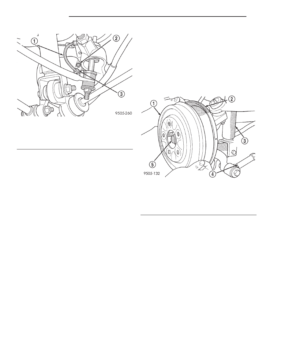
(6) If vehicle is equipped with ABS brakes, install
speed sensor head into rear brake support plate (Fig.
18). Torque speed sensor head mounting bolt to 7
N·m (60 in. lbs.).
Fig. 14 Removing Ball Joint Stud From Knuckle
1 – BALL JOINT
2 – SPECIAL TOOL CT1106
3 – BALL JOINT STUD
4 – KNUCKLE
Fig. 15 Trailing Link Attachment To Rear Knuckle
1 – TENSION NUT
2 – WRENCH
3 – KNUCKLE
Fig. 16 Shock Absorber Attachment To Knuckle
1 – SHOCK ABSORBER CLEVIS BRACKET
2 – KNUCKLE
Fig. 17 Trailing Link Bushing And Retainer
Installation
1 – FORWARD LATERAL ARM
2 – REAR LATERAL ARM
3 – NUT
4 – KNUCKLE
5 – OUTER TRAILING LINK RETAINER (GOLD)
6 – INNER TRAILING LINK BUSHING
7 – INNER TRAILING LINK RETAINER (BLACK)
8 – TRAILING LINK
9 – OUTER TRAILING LINK BUSHING
JX
SUSPENSION
2 - 55
REMOVAL AND INSTALLATION (Continued)
(7) Attach routing bracket for speed sensor cable
to brake flex hose bracket and securely tighten
attaching bolt (Fig. 7).
(8) Install park brake cable into brake support
plate. Ensure cable retainer is securely holding cable
to support plate. Then connect park brake cable to
park brake lever on brake shoe.
(9) Install rear hub and bearing assembly on
knuckle and install hub and bearing assembly retain-
ing nut. Tighten retaining nut to a torque of 250 N·m
(185 ft. lbs).
(10) Install the brake drum on the hub/bearing
assembly.
(11) Install wheel and tire assembly on vehicle.
Tighten the wheel mounting stud nuts in proper
sequence until all nuts are torqued to half specifica-
tion. Then repeat the tightening sequence to the full
specified torque of 135 N·m (100 ft. lbs.).
(12) Lower vehicle.
(13) Check and reset rear wheel alignment to spec-
ifications if required. Refer to Front And Rear Align-
ment Setting Procedure in the Wheel Alignment
Check And Adjustment section in this group of the
service manual for the required alignment setting
procedure.
HUB AND BEARING (REAR)
REMOVAL
(1) Raise vehicle on jackstands or centered on a
frame contact type hoist. See Hoisting in the Lubri-
cation and Maintenance section of this manual for
the required lifting procedure to be used for this
vehicle.
(2) Remove rear wheel and tire assembly.
(3) If equipped with rear drum brakes, remove
brake drum (Fig. 19) from rear hub and bearing
assembly by removing the clips, then pulling the
drum straight off the wheel mounting studs. If
equipped with rear disc brakes, remove the rear cal-
iper following the procedure found in REMOVAL
AND INSTALLATION of the BASE BRAKE SYS-
TEM section of the group BRAKES. Remove the
brake rotor by pulling the rotor straight off the wheel
mounting studs.
(4) Remove dust cap from rear hub and bearing
assembly by prying it off.
(5) Remove hub and bearing assembly to rear spin-
dle retaining nut (Fig. 20).
(6) Remove rear hub and bearing from the spindle
by pulling it straight off the spindle by hand.
INSTALLATION
(1) Install the hub and bearing assembly on the
knuckle spindle. Install a NEW retaining nut (Fig.
20). Tighten the retaining nut to a torque of 250 N·m
(185 ft. lbs.).
(2) Install the hub and bearing dust cap using a
soft faced hammer.
(3) Install the brake drum or brake rotor on the
hub and bearing.
(4) If equipped with rear disc brakes, install the
rear
caliper
following
the
procedure
found
in
REMOVAL AND
INSTALLATION
of
the
BASE
BRAKE SYSTEM section of the group BRAKES.
(5) Install the rear tire and wheel assembly on
vehicle. Tighten all wheel stud nuts in criss-cross
Fig. 18 Speed Sensor Head Attachment To Brake
Support Plate
1 – SPEED SENSOR CABLE
2 – BOLT
3 – SPEED SENSOR HEAD
Fig. 19 Rear Brake Drum Removal
1 – REAR BRAKE DRUM
2 – REAR BRAKE SUPPORT PLATE
3 – SHOCK ASSEMBLY
4 – REAR LATERAL ARM
5 – HUB/BEARING ASSEMBLY
2 - 56
SUSPENSION
JX
REMOVAL AND INSTALLATION (Continued)
Нет комментариевНе стесняйтесь поделиться с нами вашим ценным мнением.
Текст