
Chrysler Stratus Convertible. Manual — part 225
INSTALLATION
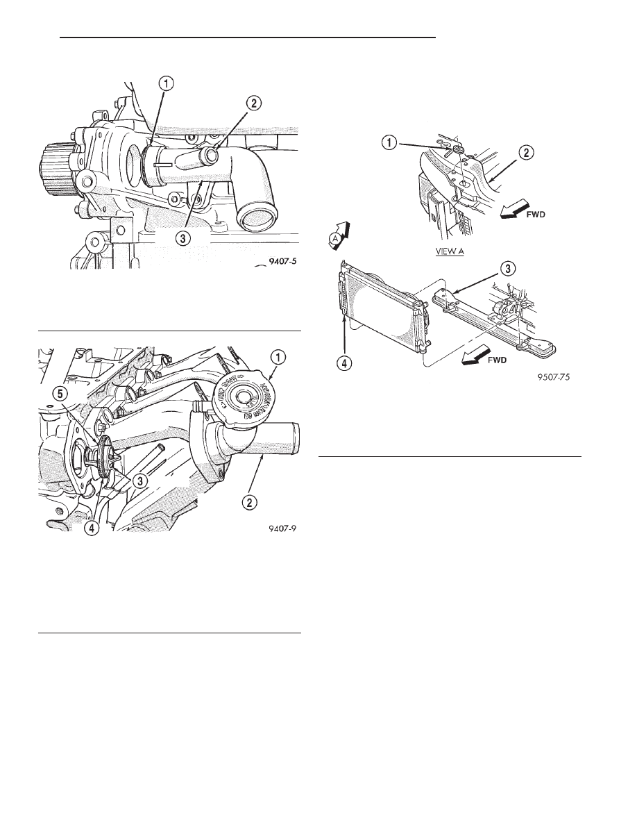
(1) Place the new thermostat assembly into the
engine outlet connector. Align air bleed with notch on
the cylinder head.
(2) Install engine outlet connector onto cylinder
head and tighten bolts to 12.5 N·m (110 in. lbs.).
Connect the coolant recovery system (CRS) hose.
(3) Fill cooling system. Refer to Cooling System
Refilling in this section.
RADIATOR
REMOVAL
(1) Disconnect
negative
cable
from
auxiliary
jumper terminal.
(2) Remove air inlet resonator. Refer to Group 14,
Fuel System for procedure.
WARNING: DO
NOT
REMOVE
THE
CYLINDER
BLOCK PLUG OR THE RADIATOR DRAINCOCK
WITH THE SYSTEM HOT AND UNDER PRESSURE
BECAUSE SERIOUS BURNS FROM COOLANT CAN
OCCUR.
(3) Drain cooling system. Refer to Cooling System
Draining in this section.
(4) Remove upper radiator crossmember (Fig. 20).
Refer to Group 23, Body for procedure.
CAUTION: Plastic tanks, while stronger then brass
are
subject
to
damage
by
impact,
such
as
wrenches.
(5) Remove hose clamps and hoses from the radia-
tor.
(6) Disconnect the fan wiring connector.
(7) Remove fan module.
Fig. 18 Water Pump Inlet Tube—Service
1 – O-RING
2 – TO HEATER
3 – WATER PUMP INLET TUBE
Fig. 19 Thermostat/Engine Outlet Connector—2.0L
Engine
1 – PRESSURE CAP
2 – THERMOSTAT HOUSING/ENGINE OUTLET CONNECTOR
3 – THERMOSTAT
4 – O-RING
5 – VENT FACING UP
Fig. 20 Cooling Module Mounting
1 – ISOLATOR
2 – UPPER RADIATOR CROSSMEMBER
3 – LOWER RADIATOR CROSSMEMBER
4 – COOLING MODULE
JX
COOLING SYSTEM
7 - 19
REMOVAL AND INSTALLATION (Continued)
(8) Disconnect automatic transmission hoses from
cooler and plug off.
(9) Remove screw attaching support bracket for
external transmission oil cooler lines to left side of
radiator (if equipped).
(10) Disconnect the engine block heater wire, if
equipped.
CAUTION: Avoid bending the condenser inlet tube.
Care should be taken not to damage radiator or
condenser cooling fins or water tubes during
removal.
(11) Remove screw attaching support bracket for
air conditioning lines from right side of radiator.
Remove support bracket.
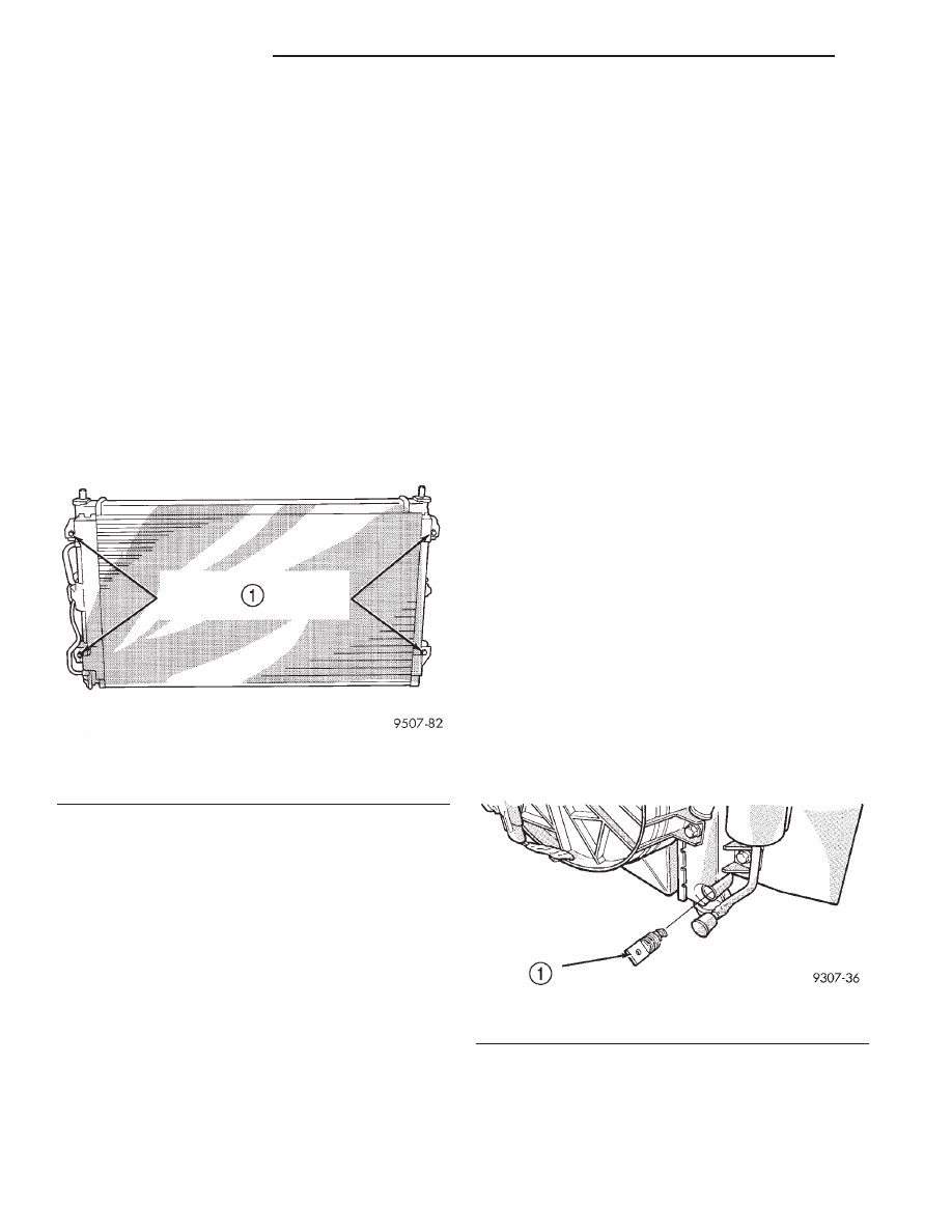
(12) Remove the air conditioning condenser attach-
ing screws located at the front of the radiator (Fig.
21), if equipped. It is not necessary to discharge the
air conditioning system to remove radiator.
(13) Radiator can now be lifted free from engine
compartment. Care should be taken not to dam-
age radiator cooling fins or water tubes during
removal.
INSTALLATION
(1) Slide radiator and fan module down into posi-
tion, seat the radiator assembly lower rubber isola-
tors in the mount holes provided.
(2) Attach air conditioning condenser to radiator, if
equipped. Tighten mounting screws to 5 N·m (45 in.
lbs.).
(3) Install air conditioning line support bracket
and attaching screw to right side of radiator.
(4) Connect engine block heater wire, if equipped.
(5) Connect lower radiator hose and clamp.
(6) Install external transmission oil cooler line
support bracket and attaching screw to left side of
radiator (if equipped).
(7) Connect automatic transmission hoses; tighten
hose clamps to 2.5 N·m (22 in. lbs.).
(8) Install fan module.
(9) Connect fan motor electrical connection.
(10) Install upper radiator hose. Align hose so it
does not interfere with the accessory drive belt or
engine. Position hose clamp so it will not interfere
with the hood liner.
(11) Install upper radiator crossmember. Refer to
Group 23, Body for procedure.
(12) Connect negative cable to auxiliary jumper
terminal.
(13) Fill cooling system with coolant. Refer to Cool-
ing System Refilling in this section.
(14) Operate engine until it reaches normal oper-
ating temperature. Check cooling system and auto-
matic transmission for correct fluid levels.
RADIATOR DRAINCOCK
REMOVAL
CAUTION: Plastic tanks, while stronger then brass
are
subject
to
damage
by
impact,
such
as
wrenches.
(1) Turn the draincock stem counterclockwise to
unscrew the stem. When the stem is unscrewed to
the end of the threads, pull the stem (Fig. 22) from
the radiator tank.
NOTE: To open draincock on vehicle equipped with
2.5L engine, use a 3/8 inch drive extension 3” long,
a 19mm socket with universal.
INSTALLATION
(1) Push the draincock assembly body into the
tank opening until it snaps into place.
(2) Tighten the draincock stem by turning clock-
wise to 2.0-2.7 N·m (18-25 in. lbs.) torque.
Fig. 21 A/C Condenser to Radiator Mounting Screws
1 – AIR CONDITIONING CONDENSER TO RADIATOR
MOUNTING SCREWS
Fig. 22 Draincock—Typical
1 – DRAIN COCK BODY
7 - 20
COOLING SYSTEM
JX
REMOVAL AND INSTALLATION (Continued)
RADIATOR FAN, MOTOR AND SHROUD
REMOVAL
(1) Remove upper radiator crossmember. Refer to
Group 23, Body for procedure.
(2) Disconnect fan motor electrical connector.
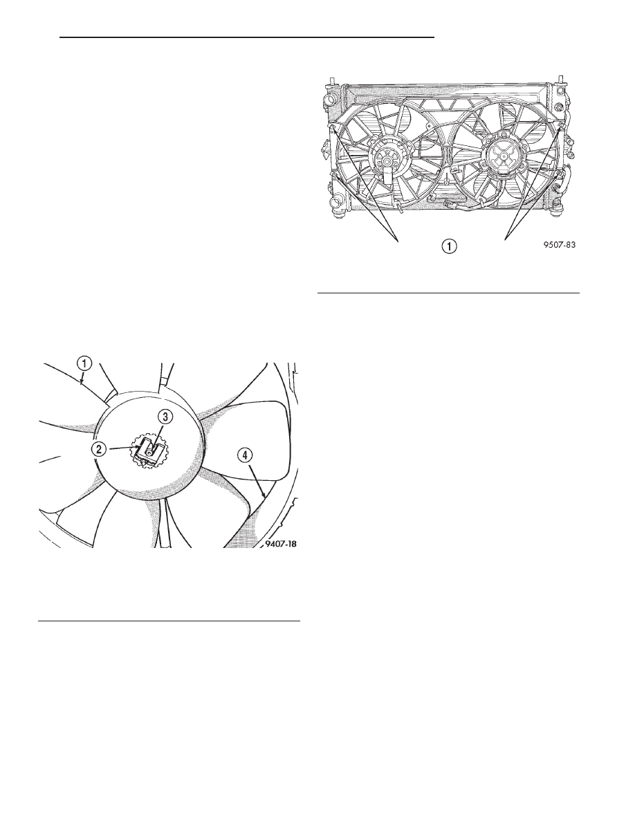
(3) Remove fasteners attaching fan module to radi-
ator (Fig. 24).
(4) Remove fan module.
FAN SERVICE
There are no repairs to be made to the fan. If the
fan is warped, cracked, or otherwise damaged, it
must be replaced with only the recommended part
for adequate strength, performance and safety.
(1) To remove fan from motor shaft, bench support
the motor and motor shaft while removing the fan
retaining clip, so that the shaft and motor will not be
damaged by excessive force. Surface burr removal
may be required to remove fan from motor
shaft (Fig. 23). Do not permit the fan blades to
touch the bench.
(2) To install fan on motor shaft, slide the fan over
the shaft. Support motor and shaft while installing
fan retaining clip.
FAN SHROUD
All vehicles have fan shrouds to improve fan air
flow efficiency.
The shroud supports the electric fan motor and
fan.
FAN MOTOR SERVICE
(1) Remove the motor fasteners from support.
Remove motor from support.
(2) Reverse the above procedure for Installation.
Tighten the short fan motor fasteners to 3 N·m (25
in. lbs.) and tighten the tall fan motor fasteners to 5
N·m (45 in. lbs.).
INSTALLATION
(1) Install fan module to radiator. Tighten shroud
to radiator fasteners to 7.5 N·m (65 in. lbs.) (Fig. 24).
(2) Connect fan motor electrical connector. For
wiring diagrams of fan motor systems, refer to
Group 8W, Wiring Diagrams.
(3) Install upper radiator crossmember. Refer to
Group 23, Body for procedure.
TRANSMISSION OIL COOLER EXTERNAL—
2.0L ENGINE
REMOVAL
(1) Remove the upper radiator crossmember.
(2) Remove the fan module. Refer to procedures in
this section.
(3) Loosen the cooler line bracket on the left side
of radiator.
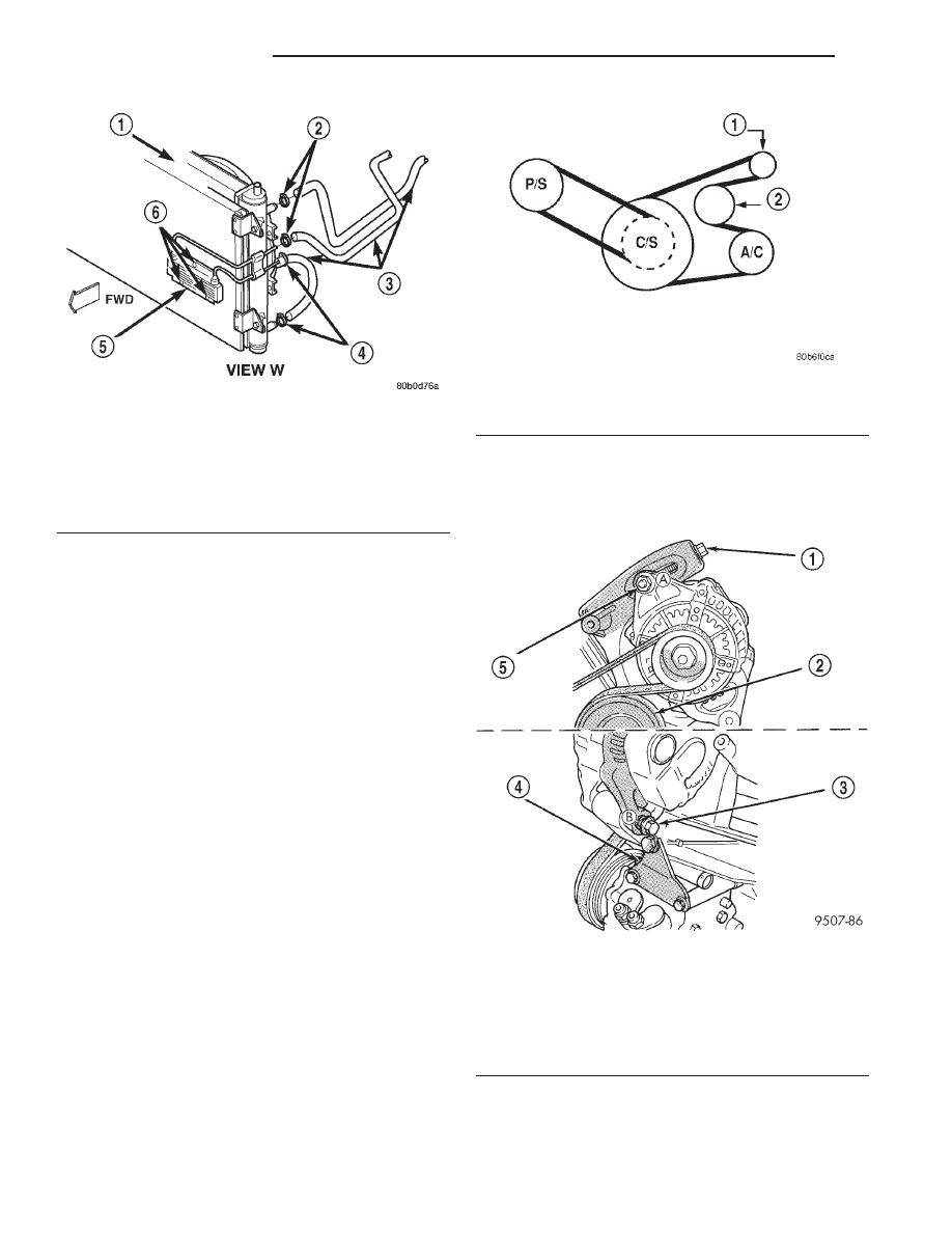
(4) Disconnect cooler lines from cooler (Fig. 25).
(5) Remove cooler (Fig. 25).
INSTALLATION
(1) Install cooler (Fig. 25).
(2) Connect cooler lines (Fig. 25).
(3) Tighten cooler line support bracket.
(4) Install cooling fan module.
(5) Install upper radiator crossmember.
(6) Check and adjust transmission oil level.
Fig. 23 Radiator Fan—Removal/Installation
1 – FAN
2 – RETAINING CLIP
3 – MOTOR SHAFT
4 – SHROUD ASSEMBLY
Fig. 24 Fan Module
1 – FAN MODULE TO RADIATOR FASTENERS
JX
COOLING SYSTEM
7 - 21
REMOVAL AND INSTALLATION (Continued)
ENGINE BLOCK HEATER
REMOVAL
(1) Drain coolant from radiator and cylinder block.
Refer to Cooling System Drain, Clean, Flush and
Refill of this section for procedure.
(2) Detach power cord plug from heater.
(3) Loosen screw in center of heater. Remove
heater assembly.
INSTALLATION
(1) Thoroughly clean core hole and heater seat.
(2) Insert heater assembly with electrical connec-
tor position at the top of the core hole.
(3) With
heater
seated,
tighten
center
screw
securely to assure a positive seal.
(4) Fill cooling system with coolant to the proper
level, vent air, and inspect for leaks. Pressurize sys-
tem with Radiator Pressure Tool before looking for
leaks.
The power cord must be secured in its retainer
clips, and not positioned so it could contact linkages
or exhaust manifolds and become damaged.
ACCESSORY DRIVE BELTS—2.0L ENGINE
AIR CONDITIONING COMPRESSOR AND
GENERATOR BELT
(1) Loosen T-Bolt locking nut (A) and pivot bolt (B)
to remove and install the Poly-V belt and/or adjust
belt tension (Fig. 26).
(2) Tighten adjusting bolt to adjust belt tension to
specification shown in Belt Tension Chart.
(3) Tighten T-Bolt locking nut (A) and pivot bolt
(B) to 54 N·m (40 ft. lbs.) (Fig. 26).
POWER STEERING PUMP BELT
(1) From the top of the vehicle loosen pivot bolt
(C).
Fig. 25 Transmission Oil Cooler—2.0L Engine
1 – COOLING MODULE
2 – HOSE CLAMPS
3 – TRANSMISSION OIL COOLER HOSES
4 – HOSE CLAMPS
5 – EXTERNAL TRANSMISSION OIL COOLER
6 – RETAINING STRAPS
Accessory Drive Belt System—2.0L Engines
1 – GEN.
2 – IDLER
Fig. 26 Air Conditioning Compressor and Generator
Belt Adjustment
1 – ADJUSTING BOLT
2 – IDLER
3 – PIVOT BOLT
4 – SUPPORT BRACKET
5 – LOCK NUT
7 - 22
COOLING SYSTEM
JX
REMOVAL AND INSTALLATION (Continued)
Нет комментариевНе стесняйтесь поделиться с нами вашим ценным мнением.
Текст