
Chrysler Stratus Convertible. Manual — part 161
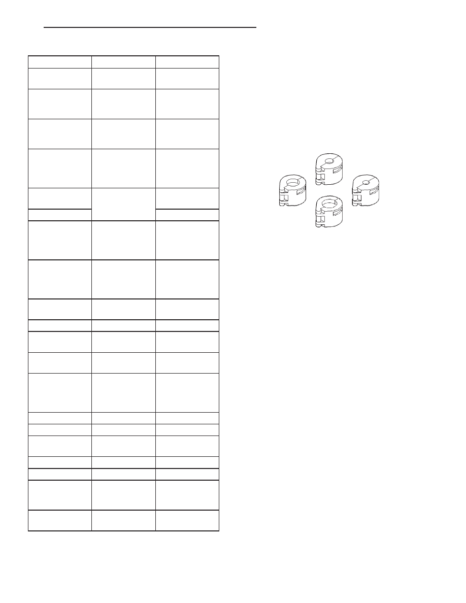
THERMAL LIMITER SWITCH
DESCRIPTION
TEMPERATURE
Cut OFF Temperature . . . 122 to 128°C (252 to 262°F)
Cut IN Temperature . . . . 104 to 116°C (225 to 235°F)
SPECIAL TOOLS
AIR CONDITIONING
Item
Description
Notes
VEHICLE
Sebring
Convertible
2-door
convertible
SYSTEM
R134a
w/expansion
valve
COMPRESSOR
Sanden
TRS-090
(Scroll)
SP-15 PAG Oil
Freeze–up
Control
evaporator
temp probe
(2-wire)
BCM input,
signals OFF <
33.7° F, ON >
35.7° F
Low psi Control
pressure
transducer to
PCM
opens < 29.4
psi
High psi Control
opens > 431 psi
Thermal Limiter
Switch
cut Out >
252-262° F, cut
In < 225-235° F
scroll
compressors
only serviced
with clutch
CONTROL
HEAD
manual type
resistive
multiplex signal
for A/C request
to BCM
Mode Door
electric actuator
w/feedback
BCM controlled
Blend Air Door
cable
Fresh/Recirc
door
cable
Blower Motor
hardwired to
control head
resistor block
COOLING
FANS
PCM controlled
module, two fan
motors -
low/high
low & high
relays
CLUTCH
Control
relay
PCM
Draw
2-4.15 amps @
12V
6
0.5V
Gap
0.013
9
-0.025
9
DRB III
T
Reads
Mode door,
TPS, RPM, A/C
switch test
Actuators
clutch and fan
relays
A/C Line Disconnect Tool 7193
JX
HEATING AND AIR CONDITIONING
24 - 41
SPECIFICATIONS (Continued)
EMISSION CONTROL SYSTEMS
TABLE OF CONTENTS
page
page
ON-BOARD DIAGNOSTICS . . . . . . . . . . . . . . . . . . . 1
EVAPORATIVE EMISSION CONTROLS . . . . . . . . . 22
EXHAUST GAS RECIRCULATION (EGR)
SYSTEM . . . . . . . . . . . . . . . . . . . . . . . . . . . . . . . 32
ON-BOARD DIAGNOSTICS
TABLE OF CONTENTS
page
page
DESCRIPTION AND OPERATION
SYSTEM DESCRIPTION . . . . . . . . . . . . . . . . . . . . 1
MALFUNCTION INDICATOR LAMP (MIL) . . . . . . . . 2
DRB III STATE DISPLAY TEST MODE . . . . . . . . . . 2
DRB III CIRCUIT ACTUATION TEST MODE . . . . . . 2
DIAGNOSTIC TROUBLE CODES . . . . . . . . . . . . . . 2
DIAGNOSTIC TROUBLE CODE
DESCRIPTIONS . . . . . . . . . . . . . . . . . . . . . . . . . 3
MONITORED SYSTEMS. . . . . . . . . . . . . . . . . . . . 12
TRIP DEFINITION . . . . . . . . . . . . . . . . . . . . . . . . 16
MONITORED COMPONENT . . . . . . . . . . . . . . . . . 16
NON-MONITORED CIRCUITS . . . . . . . . . . . . . . . 20
HIGH AND LOW LIMITS . . . . . . . . . . . . . . . . . . . . 21
SPECIFICATIONS
LOAD VALUE . . . . . . . . . . . . . . . . . . . . . . . . . . . . 21
DESCRIPTION AND OPERATION
SYSTEM DESCRIPTION
OPERATION
The Powertrain Control Module (PCM) monitors
many different circuits in the fuel injection, ignition,
emission and engine systems. If the PCM senses a
problem with a monitored circuit often enough to
indicate an actual problem, it stores a Diagnostic
Trouble Code (DTC) in the PCM’s memory. If the
code applies to a non-emissions related component or
system, and the problem is repaired or ceases to
exist, the PCM cancels the code after 40 warmup
cycles. Diagnostic trouble codes that affect vehicle
emissions illuminate the Malfunction Indicator Lamp
(MIL). Refer to Malfunction Indicator Lamp in this
section.
Certain criteria must be met before the PCM
stores a DTC in memory. The criteria may be a spe-
cific range of engine RPM, engine temperature,
and/or input voltage to the PCM.
The PCM might not store a DTC for a monitored
circuit even though a malfunction has occurred. This
may happen because one of the DTC criteria for the
circuit has not been met. For example, assume the
diagnostic trouble code criteria requires the PCM to
monitor the circuit only when the engine operates
between 750 and 2000 RPM. Suppose the sensor’s
output circuit shorts to ground when engine operates
above 2400 RPM (resulting in 0 volt input to the
PCM). Because the condition happens at an engine
speed above the maximum threshold (2000 rpm), the
PCM will not store a DTC.
There are several operating conditions for which
the PCM monitors and sets DTC’s. Refer to Moni-
tored Systems, Components, and Non-Monitored Cir-
cuits in this section.
NOTE: Various diagnostic procedures may actually
cause a diagnostic monitor to set a DTC. For
instance, pulling a spark plug wire to perform a
spark test may set the misfire code. When a repair
is completed and verified, use the DRB scan tool to
erase all DTC’s and extinguish the MIL.
Technicians can display stored DTC’s by using the
DRB scan tool. Refer to Diagnostic Trouble Codes in
this section. For DTC information, refer to charts in
this section.
JX
EMISSION CONTROL SYSTEMS
25 - 1
MALFUNCTION INDICATOR LAMP (MIL)
OPERATION
As a functional test, the Malfunction Indicator
Lamp (MIL) illuminates at key-on before engine
cranking. Whenever the Powertrain Control Module
(PCM) sets a Diagnostic Trouble Code (DTC) that
affects vehicle emissions, it illuminates the MIL. If a
problem is detected, the PCM sends a message over
the CCD Bus to the instrument cluster to illuminate
the lamp. The PCM illuminates the MIL only for
DTC’s that affect vehicle emissions. The MIL stays
on continuously when the PCM has entered a
Limp-In mode or identified a failed emission compo-
nent or system. The MIL remains on until the DTC
is erased. Refer to the Diagnostic Trouble Code
charts in this group for emission related codes.
Also, the MIL either flashes or illuminates contin-
uously when the PCM detects active engine misfire.
Refer to Misfire Monitoring in this section.
Additionally, the PCM may reset (turn off) the MIL
when one of the following occur:
• PCM does not detect the malfunction for 3 con-
secutive trips (except misfire and fuel system moni-
tors).
• PCM does not detect a malfunction while per-
forming three successive engine misfire or fuel sys-
tem tests. The PCM performs these tests while the
engine is operating within
6 375 RPM of and within
10 % of the load of the operating condition at which
the malfunction was first detected.
DRB III STATE DISPLAY TEST MODE
OPERATION
The switch inputs to the Powertrain Control Mod-
ule (PCM) have two recognized states; HIGH and
LOW. For this reason, the PCM cannot recognize the
difference between a selected switch position versus
an open circuit, a short circuit, or a defective switch.
If the State Display screen shows the change from
HIGH to LOW or LOW to HIGH, assume the entire
switch circuit to the PCM functions properly. From
the state display screen, access either State Display
Inputs and Outputs or State Display Sensors.
DRB III CIRCUIT ACTUATION TEST MODE
OPERATION
The Circuit Actuation Test Mode checks for proper
operation of output circuits or devices the Powertrain
Control Module (PCM) may not internally recognize.
The PCM attempts to activate these outputs and
allow an observer to verify proper operation. Most of
the tests provide an audible or visual indication of
device operation (click of relay contacts, fuel spray,
etc.). Except for intermittent conditions, if a device
functions properly during testing, assume the device,
its associated wiring, and driver circuit work cor-
rectly.
DIAGNOSTIC TROUBLE CODES
DESCRIPTION
A Diagnostic Trouble Code (DTC) indicates the
PCM has recognized an abnormal condition in the
system.
Remember that DTC’s are the results of a sys-
tem or circuit failure, but do not directly iden-
tify the failed component or components.
NOTE: For a list of DTC’s, refer to the charts in this
section.
OPERATION
BULB CHECK
Each time the ignition key is turned to the ON
position, the malfunction indicator (check engine)
lamp on the instrument panel should illuminate for
approximately 2 seconds then go out. This is done for
a bulb check.
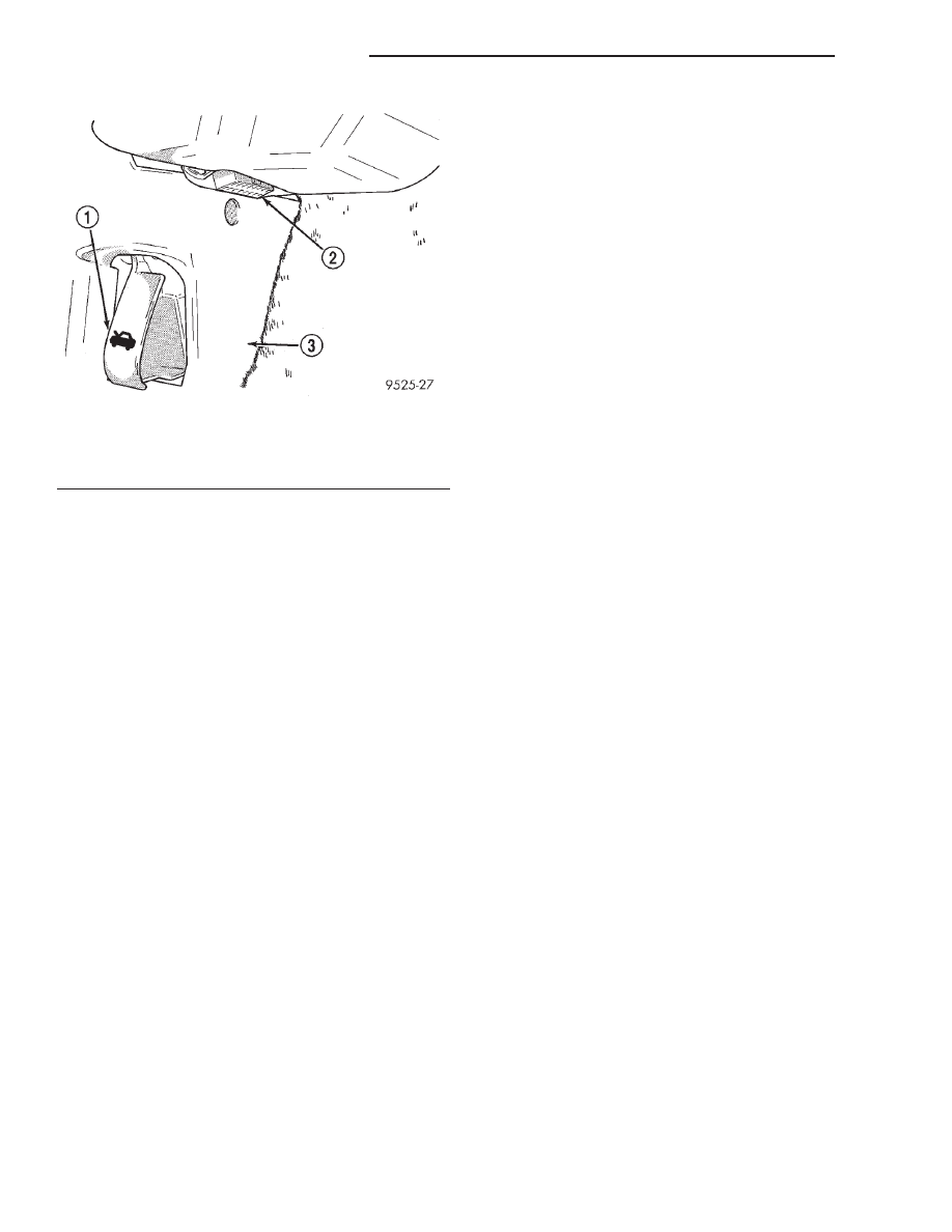
OBTAINING DTC’S USING DRB SCAN TOOL
(1) Connect the DRB scan tool to the data link
(diagnostic) connector. This connector is located in
Fig. 1 Data Link (Diagnostic) Connector
1 – HOOD RELEASE
2 – DIAGNOSTIC CONNECTOR
3 – DRIVER’S SIDE KICK PANEL
25 - 2
EMISSION CONTROL SYSTEMS
JX
DESCRIPTION AND OPERATION (Continued)
Нет комментариевНе стесняйтесь поделиться с нами вашим ценным мнением.
Текст