
Chrysler Stratus Convertible. Manual — part 39
ASSEMBLE
(1) Install power steering pump on mounting
bracket. Install the power steering pump to mounting
bracket attaching bolts. Torque the mounting bolts to
54 N·m (40 ft. lbs).
CAUTION: Do not hammer on power steering pump
pulley or shaft to remove power steering pump pul-
ley. This will damage the pulley and the power
steering pump.
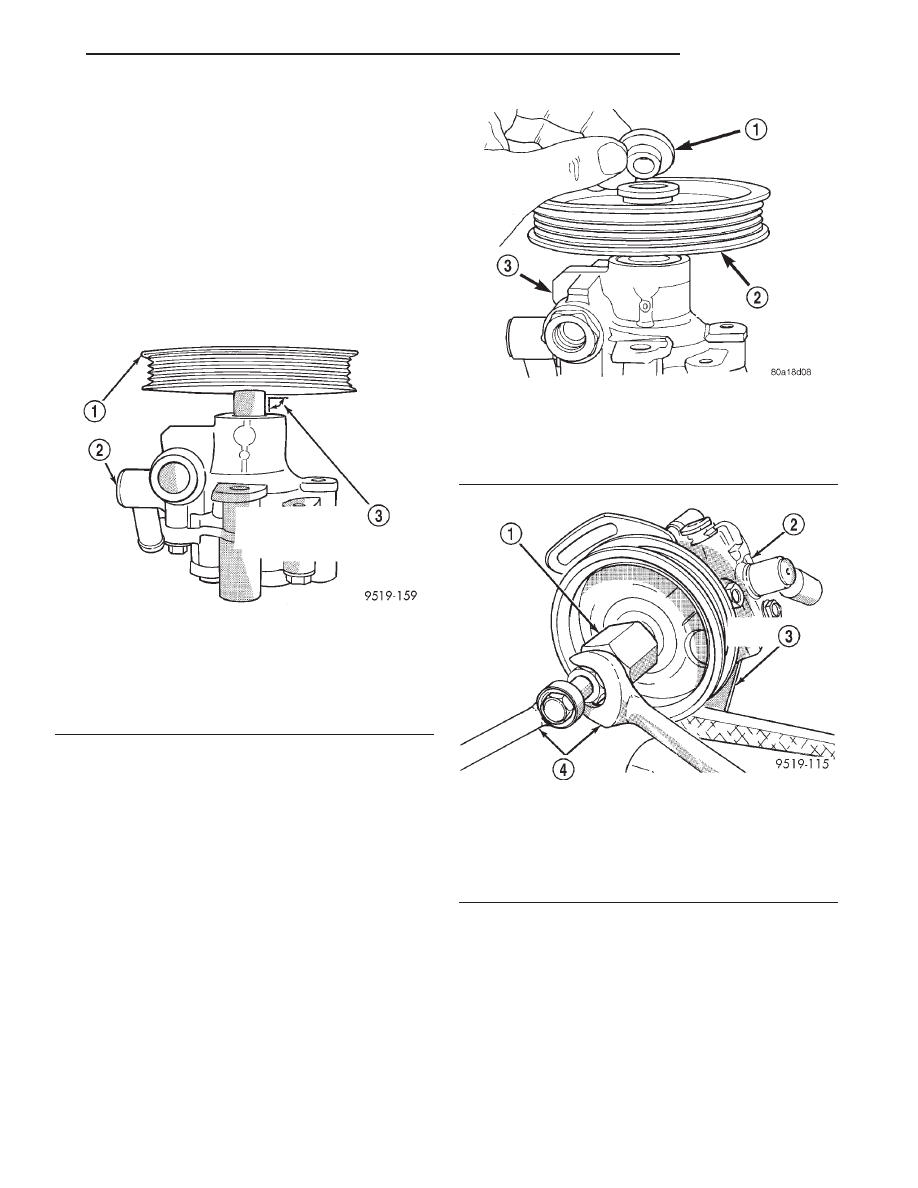
(2) Place power steering pump pulley squarely on
end of power steering pump shaft (Fig. 25).
(3) Place Installation Spacer, Special Tool 6936 on
top of the power steering pump pulley (Fig. 26).
(4) Mount Installer, Special Tool C-4063 in internal
threads of the power steering pump shaft and
against Special Tool 6936 on power steering pump
pulley (Fig. 27).
(5) Ensuring that special tool and pulley remain
aligned with pump shaft, force pulley onto power
steering pump shaft until Special Tool 6936 is
against the end of the shaft. When Special Tool
6936 is against the shaft of the power steering
pump, Special Tool C-4063 will no longer be
able to be turned.
(6) Remove Installer, Special Tool C-4063 from
power steering pump.
(7) Install
power
steering
pump
and
bracket
assembly back on engine. Refer to Power Steering
Pump Installation in the Power Steering Pump Ser-
vice Procedures section in this group of the service
manual for required procedure.
Fig. 25 Pulley Positioned On Shaft Of Power
Steering Pump
1 – POWER STEERING PUMP PULLEY
2 – POWER STEERING PUMP
3 – POWER STEERING PUMP PULLEY MUST BE STARTED
SQUARELY ON SHAFT OF POWER STEERING PUMP AS
SHOWN
Fig. 26 Spacer Correctly Installed On Power
Steering Pump Pulley
1 – SPECIAL TOOL 6936
2 – POWER STEERING PUMP PULLEY
3 – POWER STEERING PUMP
Fig. 27 Installing Pulley On Shaft Of Power Steering
Pump
1 – SPECIAL TOOL C-4063
2 – POWER STEERING PUMP
3 – POWER STEERING PUMP BRACKET
4 – WRENCHES
JX
STEERING
19 - 33
DISASSEMBLY AND ASSEMBLY (Continued)
SPECIFICATIONS
POWER STEERING PUMP FLOW
SPECIFICATIONS
Flow At 1500 RPM And Minimum
Pressure . . . . . . . . . . . . . . . 4.9 to 5.3 Liters/Min
(1.3 to 1.4 GPM)
Control Valve Pressure Relief . . . 8240 to 8920 kPa
(1195 to 1293 psi)
POWER STEERING PUMP FASTENER TORQUE
SPECIFICATIONS
DESCRIPTION
TORQUE
POWER STEERING PUMP:
Discharge Fitting . . . . . . . . . . 75 N·m (55 ft. lbs.)
Rear Bracket Mounting Bolts . . . . . . . . . 54 N·m
(40 ft. lbs.)
Front Bracket Mounting Bolts . . . . . . . . . 54 N·m
(40 ft. lbs.)
Bracket To Engine Mounting Bolts . . . . . 54 N·m
(40 ft. lbs.)
POWER STEERING FLUID HOSES:
Hose Tube Nuts . . . . . . . . . . 31 N·m (275 in. lbs.)
Pressure Hose To Cylinder Head 2.5L . . . 54 N·m
(40 ft. lbs.)
Return Hose To Pressure Hose
Bracket 2.5L . . . . . . . . . . . . . . 9 N·m (75 in. lbs.)
POWER STEERING FLUID RESERVOIR:
Reservoir To Mounting Bracket
Or Engine . . . . . . . . . . . . . . . 28 N·m (21 ft. lbs.)
Reservoir Bracket
To Engine . . . . . . . . . . . . . . . 28 N·m (21 ft. lbs.)
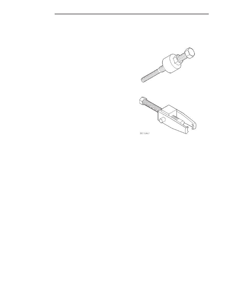
SPECIAL TOOLS
POWER STEERING PUMP
Installer C-4063B
Puller C-4333
19 - 34
STEERING
JX
POWER STEERING GEAR
TABLE OF CONTENTS
page
page
DESCRIPTION AND OPERATION
POWER STEERING GEAR. . . . . . . . . . . . . . . . . . 35
REMOVAL AND INSTALLATION
POWER STEERING GEAR. . . . . . . . . . . . . . . . . . 37
OUTER TIE ROD END . . . . . . . . . . . . . . . . . . . . . 44
DISASSEMBLY AND ASSEMBLY
POWER STEERING GEAR MOUNTING BOLT
ISOLATOR . . . . . . . . . . . . . . . . . . . . . . . . . . . . 46
SPECIFICATIONS
SPECIFICATIONS . . . . . . . . . . . . . . . . . . . . . . . 47
SPECIAL TOOLS
POWER STEERING GEAR. . . . . . . . . . . . . . . . . . 47
DESCRIPTION AND OPERATION
POWER STEERING GEAR
DESCRIPTION
The steering gear on this vehicle is a rack and pin-
ion unit with power assist (Fig. 1). It is mounted on
the front suspension crossmember. The steering col-
umn connects to the steering gear shaft on top of the
gear. The outer tie rod ends of the gear connect to
each suspension steering knuckle to steer the vehicle.
Depending on the vehicle production date, the
vehicle could use one of two power steering gears.
There is an early production steering gear and a
later production gear. Externally, the power steering
gears appear the same. Without a parts book, the
easiest way to identify whether your car is equipped
with an early or later production steering gear is to
identify what type of steering column intermediate
shaft the vehicle has. Early models use a intermedi-
ate shaft with a slap coupler connection at the steer-
ing gear pinion shaft (Fig. 2). Later models use a
slider-stage style intermediate shaft (Fig. 3).
An easy way to identify an isolated steering gear is
to look at the very end of the pinion shaft. Early
models have 2 parallel flats on the end where the
steering column intermediate shaft would bolt up
(Fig. 4). Later models have 2 flats that are at 60
degree angles to one another where the steering col-
umn intermediate shaft would bolt up (Fig. 4).
OPERATION
Turning of the steering wheel is converted into lin-
ear travel through the meshing of the helical pinion
teeth with the rack teeth. Power assist steering is
provided by an open center, rotary type control valve
which directs fluid from the pump to either side of
the integral rack piston.
Road feel is controlled by the diameter of a torsion
bar which initially steers the vehicle. This movement
directs fluid behind the integral rack piston, which,
in turn, builds up hydraulic pressure and assists in
the turning effort.
The drive tangs on the gear pinion mate loosely
with a stub shaft. This is to permit manual steering
control to be maintained if the drive belt on the
power steering pump should break. However, under
these conditions, steering effort will be increased.
JX
STEERING
19 - 35
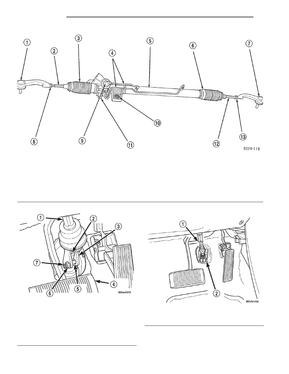
Fig. 1 Power Steering Gear
1 – TIE ROD END
2 – INNER TIE ROD
3 – STEERING GEAR BOOT
4 – STEERING GEAR FLUID LINES
5 – POWER STEERING GEAR HOUSING
6 – STEERING GEAR BOOT
7 – TIE ROD END
8 – JAM NUT
9 – STEERING GEAR SHAFT
10 – MOUNTING BUSHING
11 – POWER STEERING PRESSURE SWITCH
12 – INNER TIE ROD
13 – JAM NUT
Fig. 2 Slap Coupler Intermediate Shaft
1 – INTERMEDIATE SHAFT
2 – STEERING GEAR SHAFT
3 – COUPLER
4 – BRAKE PEDAL
5 – PINCH BOLT
6 – NUT
7 – “E” CLIP
Fig. 3 Slider-Stage Intermediate Shaft
1 – INTERMEDIATE SHAFT
2 – PINCH BOLT
19 - 36
STEERING
JX
DESCRIPTION AND OPERATION (Continued)
Нет комментариевНе стесняйтесь поделиться с нами вашим ценным мнением.
Текст