
Chrysler Stratus Convertible. Manual — part 37
washers on both sides of the hose banjo fitting once
the flow bolt is removed. Let the remaining power
steering fluid drain out of the power steering fluid
supply hose, power steering pump and power steer-
ing fluid pressure hose. After power steering fluid
has drained out of pump and hose, install a cap
on the power steering pressure hose and a plug
in the power steering pump pressure fitting.
(13) Remove the power steering pump drive belt
from power steering pump pulley.
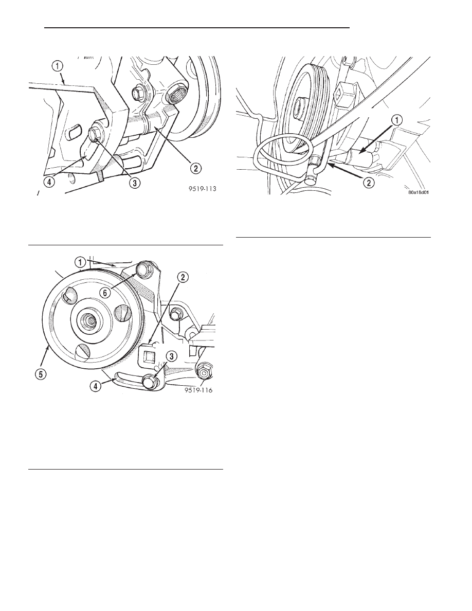
(14) Remove bolt at adjusting slot in accessory
drive mounting bracket, (Fig. 6) attaching back of
power steering pump to the bracket.
(15) Remove bolt at adjustment slot, (Fig. 7)
attaching the power steering pump front mounting
bracket to cast aluminum accessory drive bracket on
engine. Then remove bolt (Fig. 7) at top of power
steering front mounting bracket, attaching it to the
accessory drive bracket.
(16) Remove power steering pump, supply hose
and its front mounting bracket as an assembly from
the engine mounted power steering pump mounting
bracket. Place the power steering pump on top of the
antilock brakes hydraulic control unit.
NOTE: The
power
steering
pump
can
not
be
removed from the vehicle without first removing the
power steering pump mounting bracket from the
engine.
(17) Remove the 4 bolts mounting the power steer-
ing pump mounting bracket to the engine.
(18) Remove the power steering pump mounting
bracket from the engine. Position the power steering
pump mounting bracket where it will not be in the
way when removing power steering pump from the
vehicle.
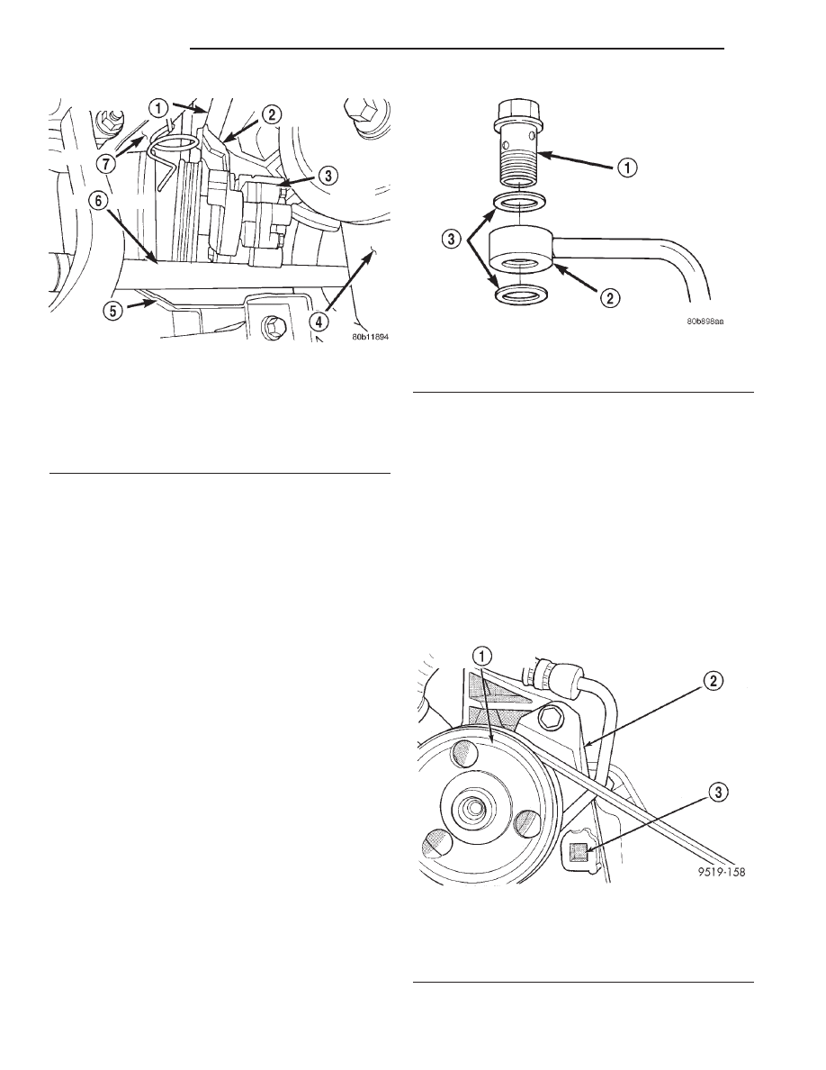
(19) Remove power steering pump, fluid supply
hose and front mounting bracket as an assembly
from the engine and vehicle. Pump, fluid supply hose
and mounting bracket is removable by bringing it out
through area between rear of engine, frame drive-
shaft and front suspension crossmember (Fig. 9).
(20) Transfer required parts from removed power
steering pump, to replacement power steering pump.
Fig. 6 Power Steering Pump Rear Mounting Bolt
1 – ACCESSORY DRIVE MOUNTING BRACKET
2 – POWER STEERING PUMP
3 – BOLT
4 – ADJUSTING SLOT
Fig. 7 Power Steering Pump Front Bracket
Attachment
1 – ENGINE ACCESSORY DRIVE BRACKET
2 – POWER STEERING PUMP FRONT MOUNTING BRACKET
3 – BOLT
4 – ADJUSTING SLOT
5 – POWER STEERING PUMP
6 – BOLT
Fig. 8 Power Steering Pressure Hose Attachment To
Pump
1 – POWER STEERING PUMP
2 – POWER STEERING PRESSURE HOSE
JX
STEERING
19 - 25
REMOVAL AND INSTALLATION (Continued)
INSTALLATION
(1) Install power steering pump, mounting bracket
and fluid supply hose as an assembly back in vehicle,
using the reverse of the removal procedure. Be sure
power steering fluid supply hose is correctly
routed up to the power steering fluid reservoir
when installing power steering pump.
(2) Place the power steering pump on top of the
antilock brakes hydraulic control unit.
(3) Install the power steering pump mounting
bracket on the rear of the engine. Tighten the mount-
ing bracket attaching bolts to a torque of 54 N·m
(40 ft. lbs.).
(4) Install power steering pump and front bracket
on engine mounted power steering pump mounting
bracket. Loosely install bolt at adjusting slot and top
of power steering pump front bracket (Fig. 7) mount-
ing pump bracket to accessory drive bracket.
(5) Loosely install the bolt mounting power steer-
ing pump to its rear mounting bracket (Fig. 6).
(6) Using a lint free towel, wipe clean all open
power steering hose ends, and power steering pump
fittings.
(7) Install a copper washer on each side of the
power steering pressure hose banjo fitting, then
install the flow bolt through the center (Fig. 10).
(8) Install the power steering pressure hose to the
power steering pump pressure fitting. Loosely install
the flow bolt into the power steering pump. Pres-
sure hose must be installed between the front
bracket of the power steering pump and the
back side of the power steering pump pulley.
(9) Install power steering pump drive belt on
power steering pump pulley.
(10) Install a 1/2 in. breaker bar in the square
adjusting hole in the front power steering pump
mounting bracket (Fig. 11) Then rotate pump to
obtain the correct drive belt tension. See Accessory
Drive Belts in Group 7 Cooling System of this service
manual for the correct drive belt tension specifica-
tion. When correct drive belt tension is obtained first
tighten the bottom 2 adjusting slot bolts at the power
steering pump cast mounting bracket to a torque of
54 N·m (40 ft. lbs.). Then tighten the power steering
pump mounting bracket top pivot bolt to a torque of
54 N·m (40 ft. lbs.).
Fig. 9 Power Steering Pump Removal/Installation
1 – SUPPLY HOSE
2 – MOUNTING BRACKET
3 – POWER STEERING PUMP
4 – ENGINE
5 – FRONT SUSPENSION CROSSMEMBER
6 – DRIVESHAFT
7 – FRAME
Fig. 10 Pressure Fitting And Washers
1 – FLOW BOLT
2 – FITTING
3 – COPPER WASHERS
Fig. 11 Power Steering Pump Front Mounting
Bracket Adjusting Hole
1 – POWER STEERING PUMP
2 – POWER STEERING PUMP MOUNTING BRACKET
3 – ADJUSTING HOLE
19 - 26
STEERING
JX
REMOVAL AND INSTALLATION (Continued)
(11) Position power steering pressure hose so hose
is not contacting the power steering pump pulley or
the drive belt. Tighten the banjo fitting flow bolt to a
torque of 47 N·m (35 ft. lbs.).
(12) Install heat shield on hydraulic control unit
(Fig. 5).
(13) Install accessory drive splash shield (Fig. 4).
(14) Install wheel and tire. Tighten the wheel lug
nuts in proper sequence until all lug nuts are
torqued to half specification. Then repeat tightening
sequence
to
full
specified
torque
of
129
N·m
(95 ft. lbs.).
(15) Lower vehicle.
(16) Install
power
steering
fluid
supply
hose
(Fig. 3) on power steering fluid reservoir fitting.
Install hose clamp on hose. Be sure hose clamp is
installed on hose past upset bead on power steering
fluid reservoir.
CAUTION: Do not use automatic transmission fluid
in power steering system. Only use Mopar
T
, Power
Steering Fluid, or equivalent.
(17) Fill power steering reservoir to correct fluid
level.
(18) Connect negative cable back on negative post
of battery.
(19) Start the engine and let run for a few seconds.
Then turn the engine off.
(20) Add fluid if necessary. Repeat the above pro-
cedure until the fluid level remains constant after
running the engine.
(21) Raise front wheels of vehicle off the ground.
(22) Start engine, then slowly turn steering wheel
right and left several times until lightly contacting
the wheel stops. Then turn the engine off.
(23) Add power steering fluid if necessary.
(24) Lower the vehicle. Start engine again and
turn the steering wheel slowly from lock to lock.
(25) Stop the engine. Check the fluid level and
refill as required.
(26) If the fluid is extremely foamy, allow the vehi-
cle to stand a few minutes and repeat the above pro-
cedure.
(27) After power steering pump is installed, check
for leaks at all hose connections and power steering
pump fittings.
POWER STEERING PUMP
(2.5L ENGINE - LATER PRODUCTION)
WARNING: POWER
STEERING
FLUID,
ENGINE
COMPONENTS AND EXHAUST SYSTEM MAY BE
EXTREMELY HOT IF ENGINE HAS BEEN RUNNING.
DO NOT START ENGINE WITH ANY LOOSE OR DIS-
CONNECTED
HOSES,
OR
ALLOW
HOSES
TO
TOUCH HOT EXHAUST MANIFOLD OR CATALYST.
REMOVAL
(1) Remove battery cable from (-) negative post on
battery and isolate cable.
(2) Siphon as much power steering fluid as possi-
ble out of the remote power steering fluid reservoir.
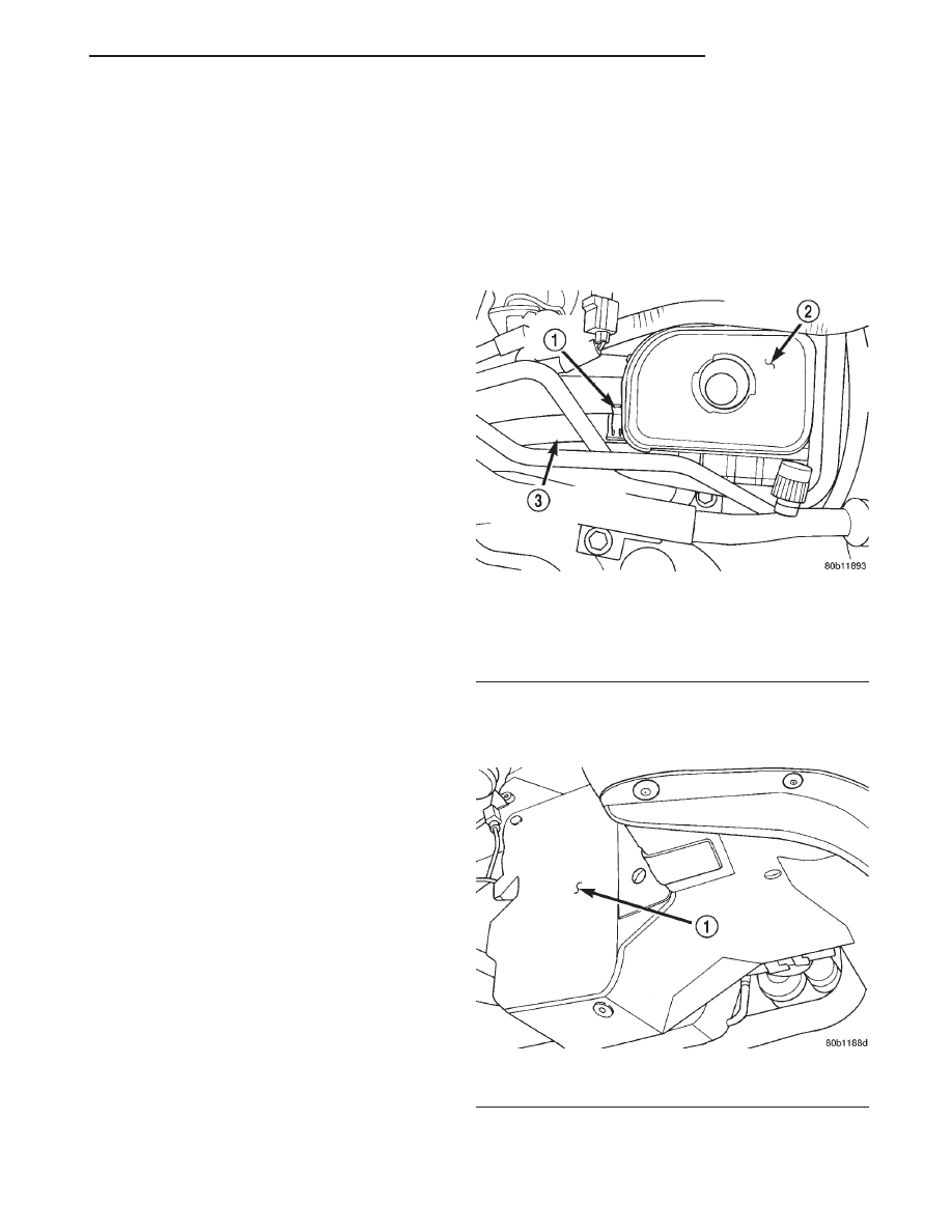
(3) Remove the power steering fluid supply hose
from the power steering fluid reservoir (Fig. 12).
Fluid supply hose will be removed with the power
steering pump.
(4) Raise vehicle.
(5) Remove right front tire from vehicle.
(6) Remove accessory drive splash shield (Fig. 13).
(7) Remove the heat shield for the antilock brakes
hydraulic control unit (Fig. 14).
Fig. 12 Supply Hose At Power Steering Fluid
Reservoir
1 – HOSE CLAMP
2 – POWER STEERING FLUID RESERVOIR
3 – POWER STEERING FLUID SUPPLY HOSE
Fig. 13 Accessory Drive Splash Shield
1 – SPLASH SHIELD
JX
STEERING
19 - 27
REMOVAL AND INSTALLATION (Continued)
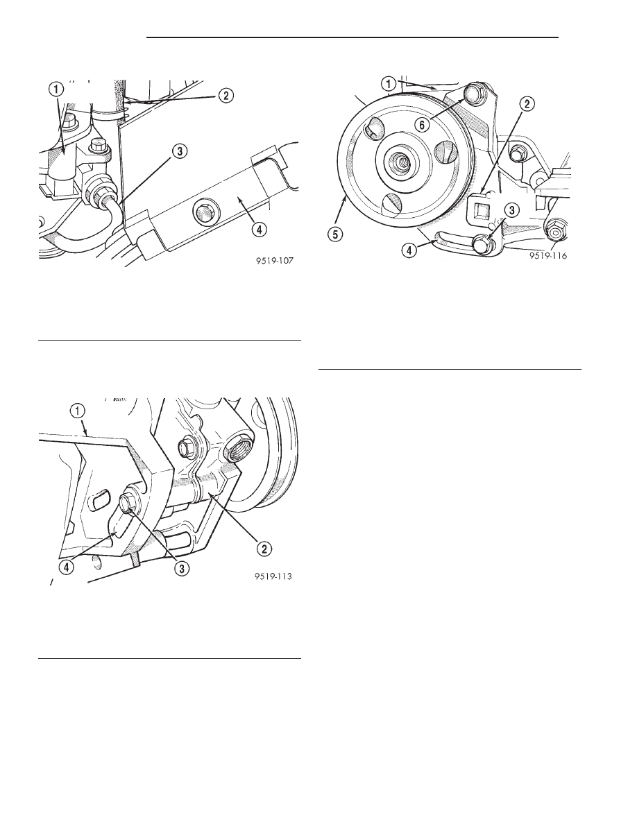
(8) Loosen bolt at adjusting slot in accessory drive
mounting bracket (Fig. 15) attaching back of power
steering pump to the bracket.
(9) Loosen bolt (Fig. 16) at top of power steering
pump front mounting bracket, attaching it to the
accessory drive bracket.
(10) Loosen bolt at adjustment slot, (Fig. 16)
attaching the power steering pump front mounting
bracket to cast aluminum accessory drive bracket on
engine.
(11) Move the power steering pump toward the
engine as far as possible.
(12) Remove the power steering fluid pressure
hose from pressure fitting on power steering pump
(Fig. 17). Be careful not to loose the copper sealing
washers on both sides of the hose banjo fitting once
the flow bolt is removed. Let the remaining power
steering fluid drain out of the power steering fluid
supply hose, power steering pump and power steer-
ing fluid pressure hose. After power steering fluid
has drained out of pump and hose, install a cap
on the power steering pressure hose and a plug
in the power steering pump pressure fitting.
(13) Remove the power steering pump drive belt
from power steering pump pulley.
(14) Remove bolt at adjusting slot in accessory
drive mounting bracket, (Fig. 15) attaching back of
power steering pump to the bracket.
(15) Remove bolt at adjustment slot, (Fig. 16)
attaching the power steering pump front mounting
bracket to cast aluminum accessory drive bracket on
engine. Then remove bolt (Fig. 16) at top of power
steering front mounting bracket, attaching it to the
accessory drive bracket.
(16) Remove power steering pump, supply hose
and its front mounting bracket as an assembly from
the engine mounted power steering pump mounting
bracket. Place the power steering pump on top of the
antilock brakes hydraulic control unit.
Fig. 14 Hydraulic Control Unit Heat Shield
1 – POWER STEERING PUMP
2 – POWER STEERING FLUID SUPPLY HOSE
3 – POWER STEERING FLUID PRESSURE HOSE
4 – ABS HYDRAULIC CONTROL UNIT HEAT SHIELD
Fig. 15 Power Steering Pump Rear Mounting Bolt
1 – ACCESSORY DRIVE MOUNTING BRACKET
2 – POWER STEERING PUMP
3 – BOLT
4 – ADJUSTING SLOT
Fig. 16 Power Steering Pump Front Bracket
Attachment
1 – ENGINE ACCESSORY DRIVE BRACKET
2 – POWER STEERING PUMP FRONT MOUNTING BRACKET
3 – BOLT
4 – ADJUSTING SLOT
5 – POWER STEERING PUMP
6 – BOLT
19 - 28
STEERING
JX
REMOVAL AND INSTALLATION (Continued)
Нет комментариевНе стесняйтесь поделиться с нами вашим ценным мнением.
Текст