
Chrysler Stratus Convertible. Manual — part 85
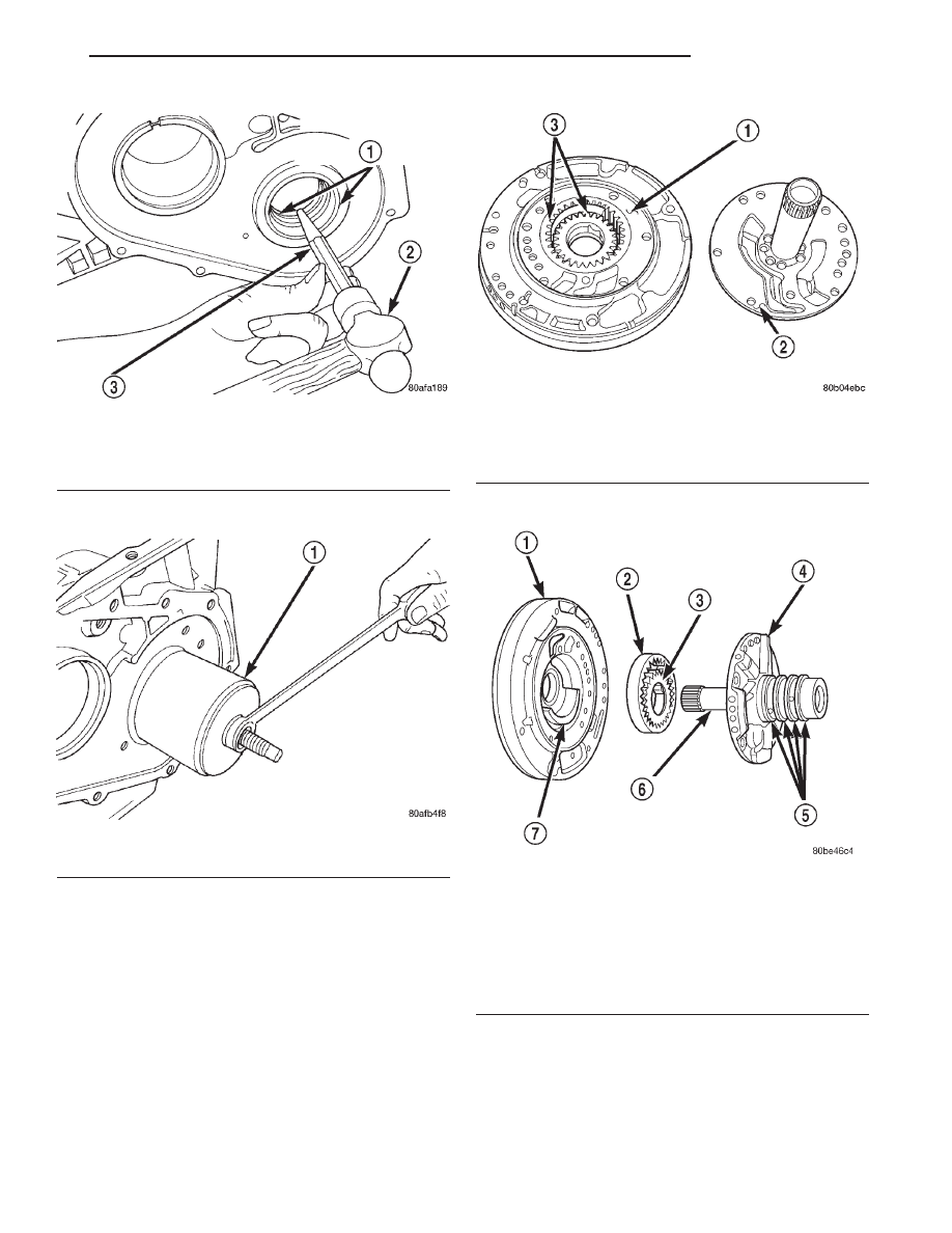
CAUTION: Drift bearing cup all the way around.
OIL PUMP
DISASSEMBLY, INSPECTION, & ASSEMBLY
When disassembling the transaxle it is necessary
to inspect the oil pump for wear and damage.
(1) Remove the reaction shaft support bolts.
(2) Remove reaction shaft support from pump
housing (Fig. 222).
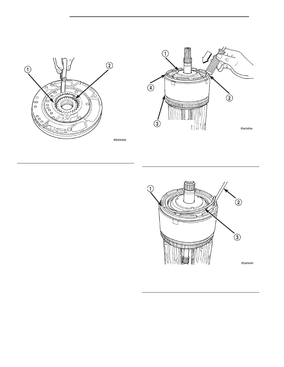
(3) Remove the pump gears (Fig. 223) and check
for wear and damage.
Fig. 220 Remove Output Bearing Inner Cup
1 – OUTPUT BEARING CUPS (REPLACE IN PAIRS)
2 – HAMMER
3 – BRASS DRIFT
Fig. 221 Remove Output Bearing Outer Cup
1 – TOOL 6062
Fig. 222 Reaction Shaft Support
1 – PUMP HOUSING
2 – REACTION SHAFT SUPPORT
3 – PUMP GEARS
Fig. 223 Oil Pump Assembly
1 – PUMP HOUSING
2 – OUTER PUMP GEAR
3 – INNER PUMP GEAR
4 – REACTION SHAFT SUPPORT
5 – SEAL RINGS (4)
6 – REACTION SHAFT
7 – CRESCENT
JX
TRANSAXLE
21 - 79
DISASSEMBLY AND ASSEMBLY (Continued)
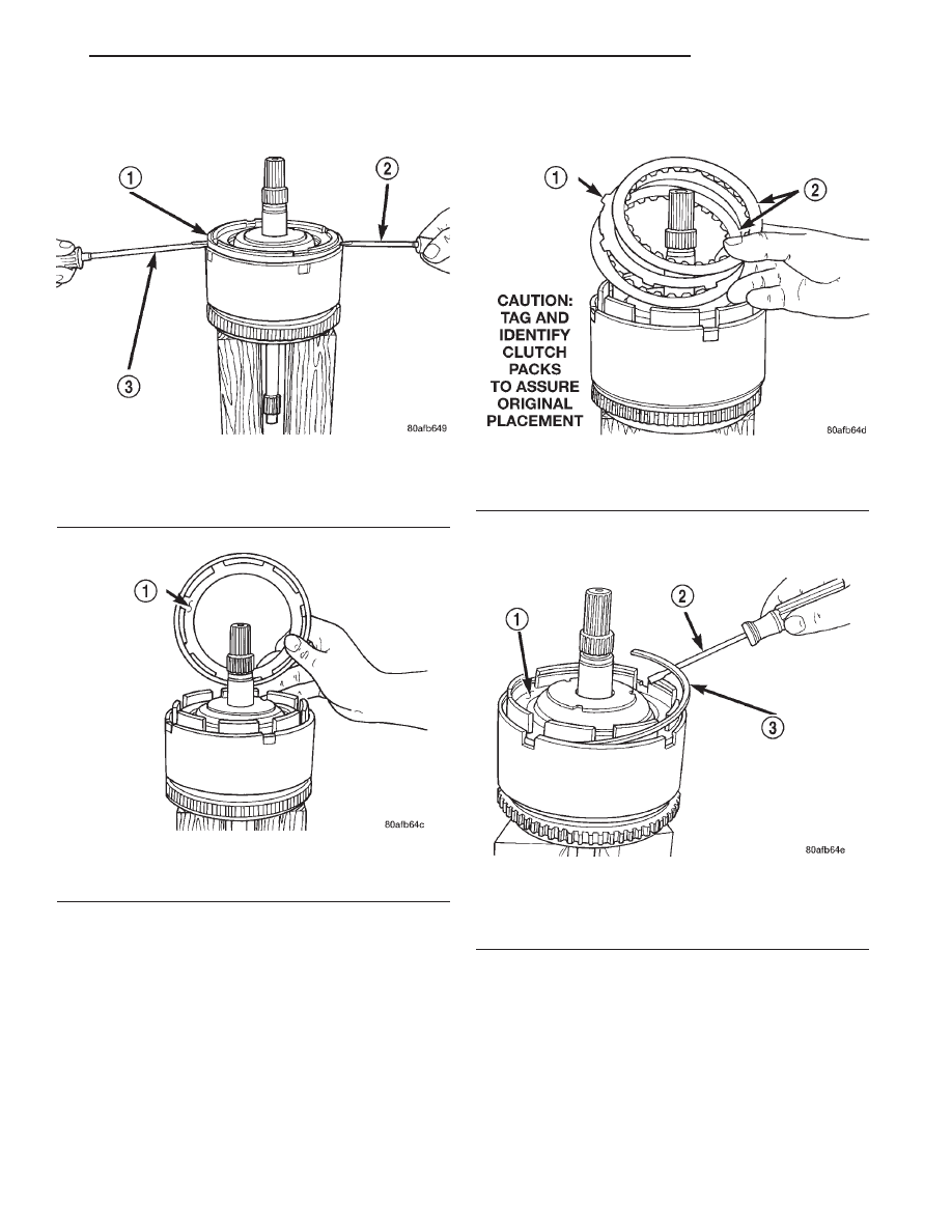
(4) Re-install the gears and check clearances.
(5) Measure the clearance between the outer gear
and the pump pocket (Fig. 224). Clearance should be
0.045-0.141mm (0.0018-0.0056 in.).
(6) Position an appropriate piece of Plastigage
across both pump gears.
(7) Align the Plastigage to a flat area on the reac-
tion shaft support housing.
(8) Install the reaction shaft to the pump housing.
Tighten the bolts to 27 N·M (20 ft. lbs.).
(9) Remove bolts and carefully separate the hous-
ings. Measure the Plastigage following the instruc-
tions supplied.
(10) Clearance between outer gear side and the
reaction shaft support should be 0.020-0.046 mm
(0.008-0.0018 in.). Clearance between inner gear side
and the reaction shaft support should be 0.020-0.046
mm (0.008-0.0018 in.).
INPUT CLUTCH ASSEMBLY
DISASSEMBLY
(1) Mount input clutch assembly to Input Clutch
Pressure Fixture (Tool 8391).
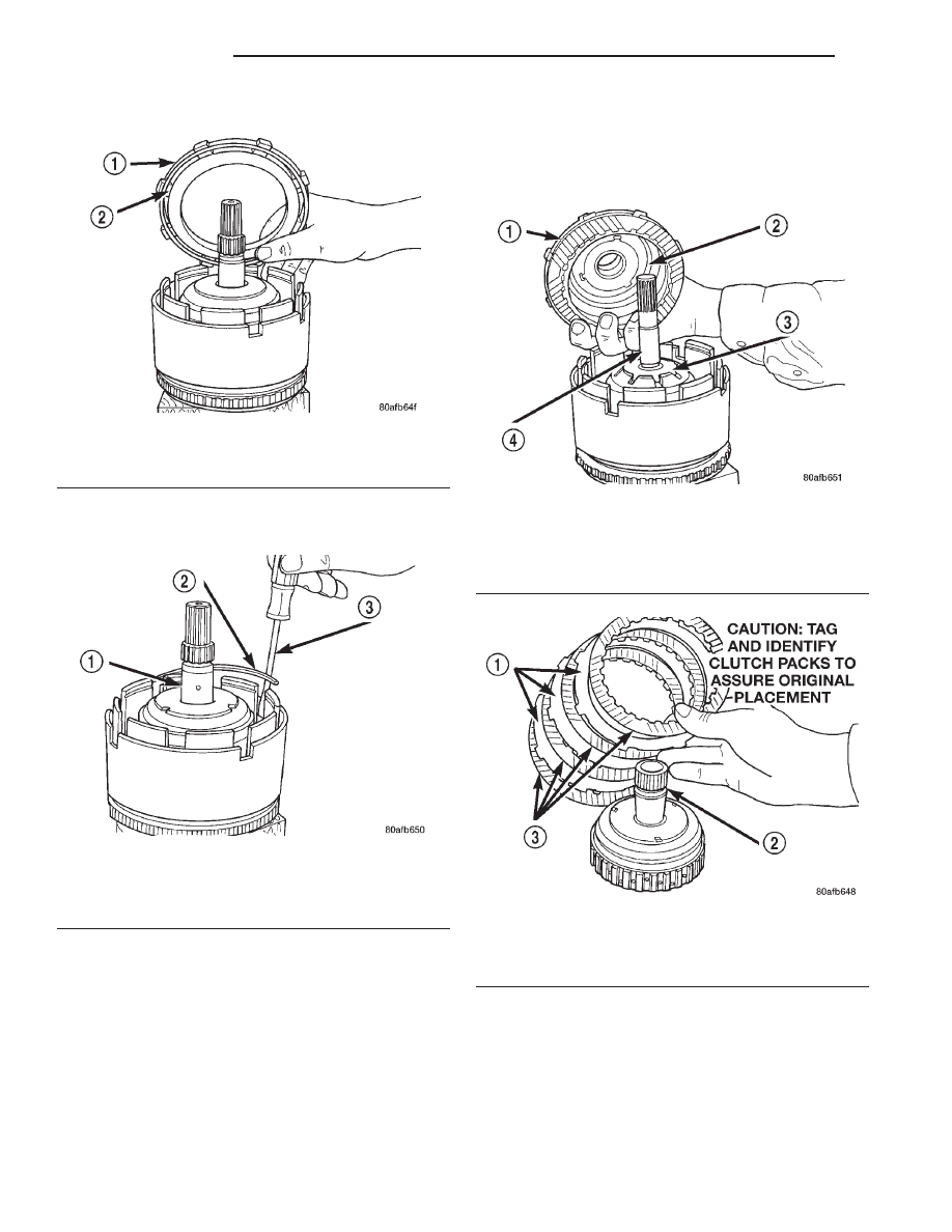
(2) Tap down reverse clutch reaction plate to
release pressure from snap ring (Fig. 225).
(3) Remove reverse clutch snap ring (Fig. 226).
Fig. 224 Measure Outer Gear to Pocket
1 – OUTER GEAR
2 – POCKET
Fig. 225 Tapping Reaction Plate
1 – #4 THRUST PLATE (SELECT)
2 – TAP DOWN REVERSE CLUTCH REACTION PLATE TO
REMOVE OR INSTALL SNAP RING
3 – INPUT SHAFT CLUTCHES RETAINER ASSEMBLY
4 – REVERSE CLUTCH REACTION PLATE
Fig. 226 Reverse Clutch Snap Ring
1 – REACTION PLATE
2 – SCREWDRIVER
3 – REVERSE CLUTCH SNAP RING (SELECT)
21 - 80
TRANSAXLE
JX
DISASSEMBLY AND ASSEMBLY (Continued)
(4) Pry up and remove reverse clutch reaction
plate (Fig. 227) (Fig. 228).
(5) Remove the reverse clutch pack (two fibers/one
steel) (Fig. 229).
NOTE: Tag reverse clutch pack for reassembly
identification.
(6) Remove the OD/Reverse reaction plate snap
ring (Fig. 230).
Fig. 227 Pry Reverse Clutch Reaction Plate
1 – REVERSE CLUTCH REACTION PLATE
2 – SCREWDRIVER
3 – SCREWDRIVER
Fig. 228 Reverse Clutch Reaction Plate
1 – REVERSE CLUTCH REACTION PLATE (INSTALL FLAT SIDE
DOWN)
Fig. 229 Reverse Clutch Pack
1 – REVERSE CLUTCH PLATE
2 – REVERSE CLUTCH DISC
Fig. 230 OD/Reverse Reaction Plate Snap Ring
1 – OD/REVERSE PRESSURE PLATE
2 – SCREWDRIVER
3 – OD/REVERSE PRESSURE PLATE SNAP RING
JX
TRANSAXLE
21 - 81
DISASSEMBLY AND ASSEMBLY (Continued)
(7) Remove OD/Reverse reaction plate (Fig. 231).
(8) Remove OD/Reverse reaction plate wave snap
ring (Fig. 232).
(9) Remove OD shaft/hub and OD clutch pack (Fig.
233) (Fig. 234).
NOTE: Tag overdrive clutch pack for reassembly
identification.
Fig. 231 OD/Reverse Reaction Plate
1 – OD/REVERSE PRESSURE PLATE (STEP SIDE DOWN)
2 – (STEP SIDE DOWN)
Fig. 232 Waved Snap Ring
1 – OVERDRIVE SHAFT ASSEMBLY
2 – OD/REVERSE CLUTCH WAVED SNAP RING
3 – SCREWDRIVER
Fig. 233 Remove OD Clutch Pack
1 – OVERDRIVE SHAFT ASSEMBLY AND OD CLUTCH PACK
2 – #3 THRUST PLATE
3 – #3 THRUST WASHER
4 – UNDERDRIVE SHAFT ASSEMBLY
Fig. 234 Overdrive Clutch Pack
1 – OVERDRIVE CLUTCH PLATE
2 – OVERDRIVE SHAFT ASSEMBLY
3 – OVERDRIVE CLUTCH DISC
21 - 82
TRANSAXLE
JX
DISASSEMBLY AND ASSEMBLY (Continued)
Нет комментариевНе стесняйтесь поделиться с нами вашим ценным мнением.
Текст