
Chrysler Stratus Convertible. Manual — part 123
NOTE: Support top 12 inches above windshield
header.
(7) Remove the five piece belt line tack strips and
save plastic centering bushings for reinstallation.
NOTE: Be sure to note the locations of the plastic
centering bushings for installation.
(8) Disengage elastic strap from the third roof bow,
if equipped.
(9) Remove antenna mast.
(10) Place protective padding over the entire rear
deck area to protect paint. Move tack strips to top of
deck opening onto protective padding.
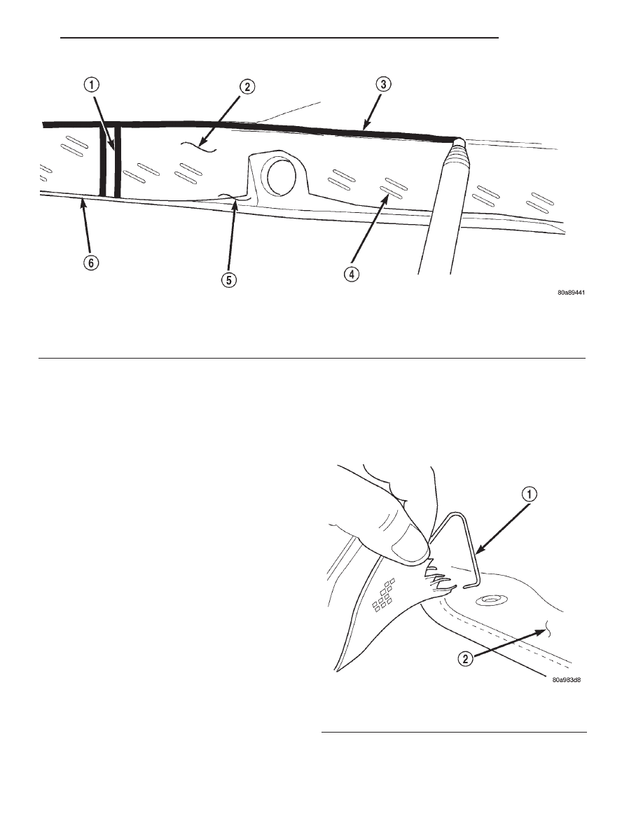
(11) Mark the outer sail panels along the top edges
and down the seams between the outer and second
tack strips from the outside of top (Fig. 1).
NOTE: Reference marks will be used to reinstall the
new rear window assembly.
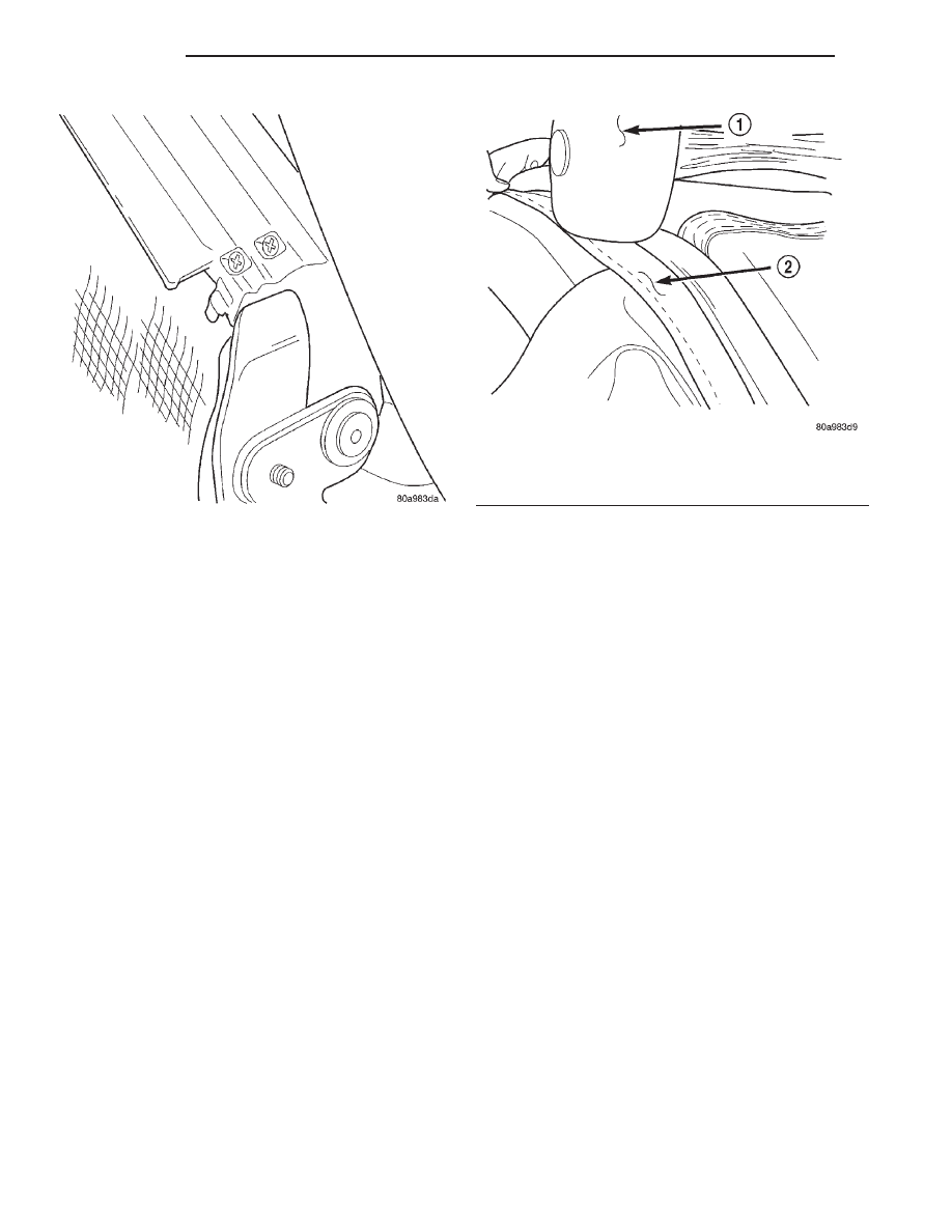
(12) Remove sail panel springs on both sides at the
front corners of the cover assembly (Fig. 2).
(13) Remove all staples from the cover assembly.
CAUTION: Be careful not to tear or damage the
cover assembly.
(14) Fold the cover assembly up over the top.
(15) Remove tape and foam at the end of the third
roof bow, save if reusable.
(16) Remove the rearmost stop screw on the number
three bow, either driver’s or passenger’s side (Fig. 3).
(17) Slide the old rear window assembly off the
number three bow.
Fig. 1 Sail Panel Reference Marks
1 – SEAM REFERENCE MARK
2 – COVER ASSEMBLY
3 – REFERENCE MARK
4 – STAPLES
5 – OUTER TACK STRIP
6 – SECOND TACK STRIP
Fig. 2 Sail Springs
1 – SAIL SPRING
2 – COVER ASSEMBLY
JX
BODY
23 - 25
REMOVAL AND INSTALLATION (Continued)
INSTALLATION
NOTE: To support the new Rear Window assembly
for stapling purposes, remove the new rear window
from packaging and place shipping box across the
top opening, resting on the back seat and decklid.
(1) Remove the boot shelf and two sail springs
from the old rear window assembly and install onto
the new rear window assembly.
(2) Place rear window locking strip on third bow.
(3) Insert the locking strip into the channel of the
number three roof bow. A rubber mallet may be
required to set locking strip into channel (Fig. 4).
CAUTION: Do not slide or pull the locking strip
onto the number three bow.
NOTE: To ensure rear window is snapped into num-
ber three bow, flip assembly onto top to inspect
snap in feature.
(4) Install existing or new foam on the end of the
bow using 1 in. black tape to secure foam to bow.
(5) Install the rearmost stop screw on the number
three bow.
(6) Starting from the right side of the vehicle,
locate the front edge of the cover assembly to the
tacking strip (use measurements located in the
Remove procedures Step 11) and pull cover down
until marking is one eighth of an inch below the top
edge of the tacking strips.
NOTE: 1/8 inch measurement should be constant
when stapling the cover assembly to prevent wrin-
kles.
(7) Continue to staple right hand cover assembly
to tacking strips. Work from the outboard to center
line of the vehicle.
(8) Repeat Step 6 for left side of the vehicle.
(9) Install sail panel springs to front of cover
assembly.
(10) Install antenna mast.
(11) Engage rear window elastic strap to number
three roof bow.
(12) Install plastic centering bushings to the belt
line tack strips.
(13) Using the nuts, install the belt line tacking
strips, starting with the center tack strip and work-
ing outboard.
(14) Feed rear window defogger wire harness
through the sleeves at each side of the rear window.
(15) Connect rear window defogger wire connectors
to terminals.
(16) Engage the headliner at the rear sail panel.
(17) Install shower curtain with push on nuts.
CAUTION: Make sure top well is not trapped under
the tack strips.
(18) Latch top and inspect for wrinkles.
Fig. 3 Rear Window Rear Stop Screw
Fig. 4 Rear Window Locking Strip
1 – RUBBER MALLET
2 – LOCKING STRIP
23 - 26
BODY
JX
REMOVAL AND INSTALLATION (Continued)
CONVERTIBLE TOP STORAGE
REMOVAL
(1) Raise and secure convertible top.
(2) Remove screws attaching headliner to top well.
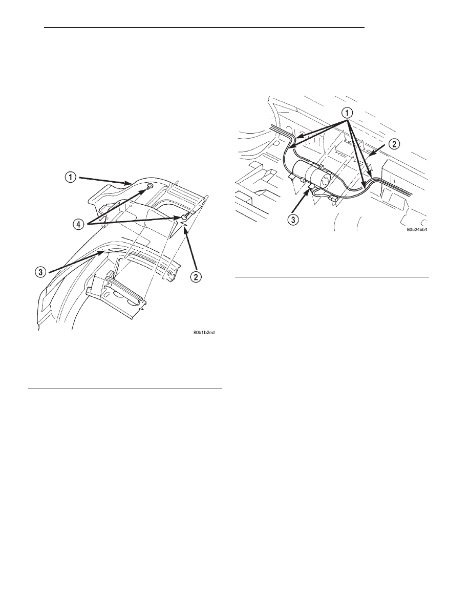
(3) Remove push in fasteners attaching convertible
top storage section to rear of storage area (Fig. 5).
(4) Remove push in fasteners attaching storage
area below seat belt bezel.
(5) Pull rear of storage area upward and disengage
front of storage area from beauty bar.
(6) Remove storage area from vehicle.
INSTALLATION
(1) Position convertible top storage area in vehicle.
(2) Engage front of storage area under beauty bar
and push rear of storage area downward into posi-
tion.
(3) Install push in fasteners attaching convertible
top storage section to rear of storage area.
(4) Install push in fasteners to attach storage
areas below seat belt bezel.
(5) Install screws attaching headliner to top well.
HYDRAULIC MOTOR/PUMP ASSEMBLY
REMOVAL
(1) Disconnect battery negative cable.
(2) Remove rear seat cushion and rear seat back.
(3) Disconnect pump wire connector and ground
connection (Fig. 6).
(4) Disconnect hydraulic lines from pump.
(5) Remove motor pump assembly from vehicle.
The rubber mounts are pressed and locked into the
mounting bracket. Pull up on motor assembly to
remove.
INSTALLATION
(1) Position hydraulic motor in vehicle.
(2) Press hydraulic motor into mounts.
(3) Connect hydraulic lines to pump.
(4) Connect pump wire connector and ground con-
nection.
(5) Connect battery negative cable.
(6) Bleed the motor/pump and fill and verify oper-
ation of hydraulic pump.
(7) Install rear seat cushion and rear seat back.
HYDRAULIC CYLINDER
REMOVAL
(1) Disconnect battery negative cable.
(2) Remove rear seat cushion and rear seat back.
(3) Remove quarter trim panel.
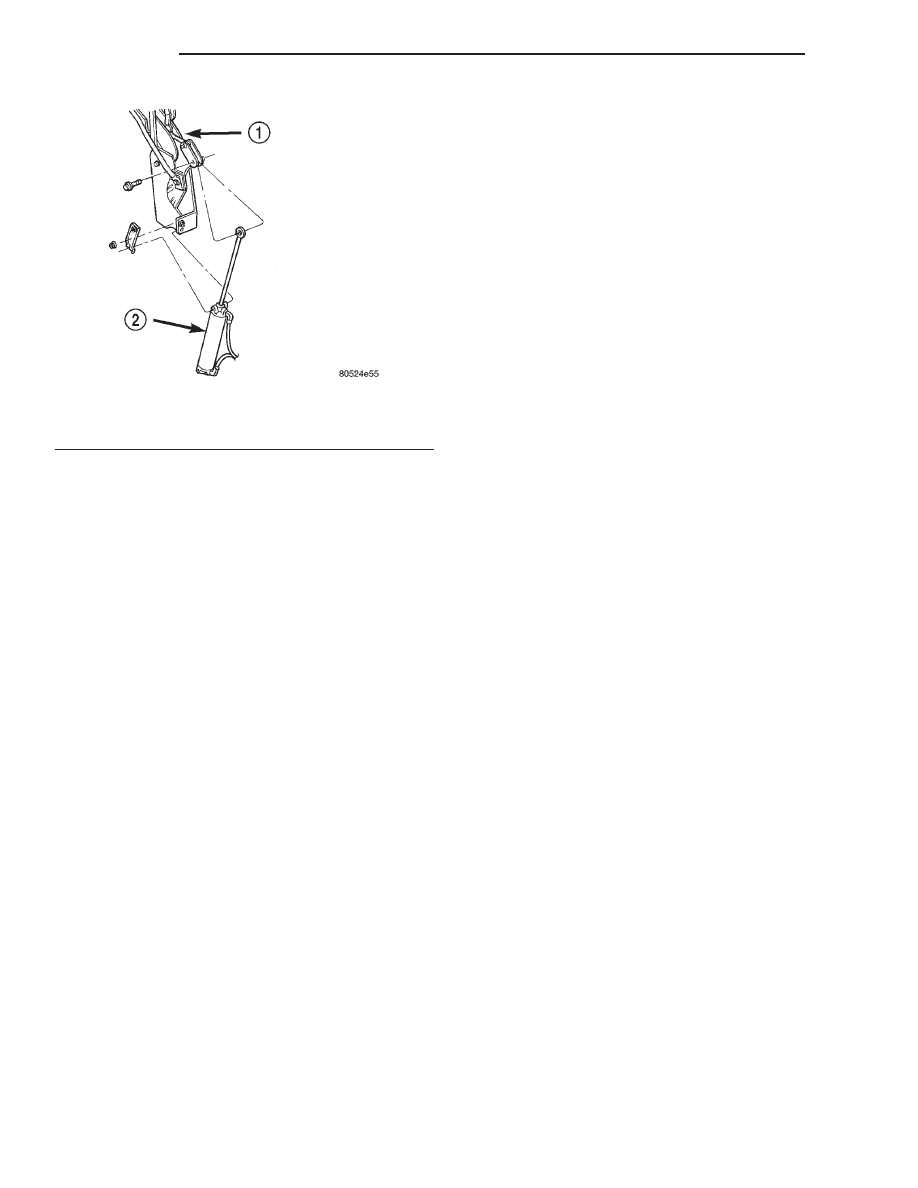
(4) Remove cylinder mounting bracket and nut
(Fig. 7).
(5) Remove pivot bolt attaching cylinder shaft to
top linkage.
(6) Disconnect hydraulic lines from the cylinder.
(7) Remove cylinder from vehicle.
INSTALLATION
(1) Place cylinder into position.
(2) Connect hydraulic lines to the cylinder.
(3) Install pivot bolt attaching cylinder shaft to top
linkage.
(4) Install cylinder mounting bracket and nut.
Fig. 5 Center Convertible Top Storage
1 – CONVERTIBLE TOP STORAGE
2 – REAR DECK PANEL
3 – TACK STRIP
4 – PUSH-IN FASTENER
Fig. 6 Hydraulic Pump Assembly
1 – HYDRAULIC LINES
2 – MOUNTING BRACKET
3 – HYDRAULIC PUMP ASSEMBLY
JX
BODY
23 - 27
REMOVAL AND INSTALLATION (Continued)
(5) Bleed the motor/pump and fill hydraulic system
and check for proper operation.
(6) Install quarter trim panel.
(7) Install rear seat cushion and rear seat back.
(8) Connect battery negative cable.
HYDRAULIC LINES
REMOVAL
(1) Remove rear seat cushion and rear seat back.
(2) Remove both quarter trim panels.
(3) Disconnect hydraulic line from hydraulic cylin-
ders.
(4) Disconnect hydraulic line from hydraulic pump.
(5) Remove hydraulic line from vehicle.
INSTALLATION
(1) Position hydraulic line to vehicle.
(2) Connect hydraulic line to hydraulic pump.
(3) Connect hydraulic line to hydraulic cylinders.
(4) Bleed the motor/pump and fill hydraulic sys-
tem. Check for leaks and proper operation.
(5) Install quarter trim panels.
(6) Install rear seat cushion and rear seat back.
ADJUSTMENTS
CONVERTIBLE TOP HYDRAULIC MOTOR/PUMP
BLEEDING PROCEDURES
Convertible top does not start to raise within 2 sec-
onds after the switch is activated. Bleed the convert-
ible top motor/pump assembly.
(1) Lower the top to the full down position.
(2) Remove the rear seat cushion, seat back and
inner quarter trim panels.
(3) Remove the cylinder mounting brackets and
remove
the
cylinders
from
the
trunnion
pivot
mounts.
(4) Rotate the cylinders 180 degrees (the hose fit-
tings will now face to front of the vehicle.
(5) Disconnect the motor/pump retaining clips from
the body.
(6) Rotate and raise the motor/pump assembly so
the reservoir is in the up position. The rubber filler
plug will be at the top.
(7) Raise motor/pump fitting to at least 2 inches
above the horizontal rear seat back reinforcement.
(8) Tilt the motor/pump assembly to approximately
the 10 o’clock position, with the rubber filler plug
still at the top.
CAUTION: THE MOTOR/PUMP ASSEMBLY MUST
REMAIN IN THE CURRENT POSITION UNTIL THE
RUBBER FILLER PLUG IS REINSTALLED IN THE
Step 12.
(9) Remove the rubber fill plug from reservoir.
(10) Fill the hydraulic system by adding Dexron 2
Automatic Transmission Fluid to the bottom of the
fill hole.
CAUTION: DO NOT OPERATE THE TOP SWITCH IN
THE UP (CLOSING THE TOP) DIRECTION.
(11) With two people, activate the top switch in the
down (opening the top) position to fully retract the
cylinder rods and hold for approximately 5 seconds,
until the motor/pump stalls. A percolating or gurgle
sound/feeling is an indication that the procedure is
working.
(12) Top off the motor/pump with Dexron 2 and
insert the filler plug.
(13) Install the motor/pump assembly into the
vehicle mounting bracket.
(14) Rotate the cylinders back to the original posi-
tion (hose fitting rearward).
(15) Install the motor/pump lead and hydraulic
line clips (the hydraulic line clips are to assist in the
production process) to ensure that the seat back/seat
cushion do not pinch the lines. If the sticky side is no
longer holding to the floor pan, the clips can be left
off.
(16) Ensure that the bushing is still on the trun-
nion pivot mount and bracket. Tap the top switch in
(raising the top) to get the cylinder trunnion onto the
trunnion pivot mounts, if needed.
(17) Install cylinder mounting brackets.
(18) Raise and lower the top to ensure proper oper-
ation.
(19) Install the inner quarter panels, and the rear
seat back and cushion.
Fig. 7 Hydraulic Cylinder
1 – CONVERTIBLE TOP LOWER PIVOT
2 – HYDRAULIC CYLINDER
23 - 28
BODY
JX
REMOVAL AND INSTALLATION (Continued)
Нет комментариевНе стесняйтесь поделиться с нами вашим ценным мнением.
Текст