
Chrysler Stratus Convertible. Manual — part 116
DIAGNOSIS AND TESTING
WHEEL INSPECTION
Wheels must be replaced if they:
• Have excessive run out
• Are bent, dented or cracked
• Leak air
• Have damaged wheel lug holes
Wheel
repairs
employing
hammering,
heating,
welding or repairing leaks are not allowed.
Original equipment replacement wheels are avail-
able through the dealer. When obtaining replacement
wheels from any other source, they must be equiva-
lent in load carrying capacity. The wheel features
(diameter, width, offset, brake clearance, and mount-
ing configuration) must match the original equip-
ment wheels.
WARNING: FAILURE TO USE ORIGINAL EQUIP-
MENT REPLACEMENT WHEELS MAY ADVERSELY
AFFECT THE SAFETY AND HANDLING OF YOUR
VEHICLE.
WARNING: REPLACEMENT WITH USED WHEELS
IS NOT RECOMMENDED. THE SERVICE HISTORY
OF THE RIM MAY HAVE INCLUDED SEVERE TREAT-
MENT OR VERY HIGH MILEAGE. THE RIM COULD
FAIL WITHOUT WARNING.
TIRE AND WHEEL RUNOUT
NOTE: Runout should always be measured off the
vehicle and on a suitable balance machine.
Radial run out is the difference between the high
and low points on the outer edge of the tire or wheel.
Lateral run out is the total side–to–side wobble of
the tire or wheel.
Radial run out of more than 1.5 mm (.060 inch)
measured at the center line of the tread may cause
the vehicle to shake.
Lateral run out of more than 2.0 mm (.080 inch)
measured at the side of the tire as close to the tread
as possible may cause the vehicle to shake.
Sometimes radial run out can be reduced by relo-
cating the wheel and tire on the wheel studs (See
Method 1). If this does not reduce run out to an
acceptable level, the tire can be rotated on the wheel.
(See Method 2).
METHOD 1 (RELOCATE WHEEL ON HUB)
Check accuracy of the wheel mounting surface;
adjust wheel bearings.
Drive vehicle a short distance to eliminate tire flat
spotting from a parked position.
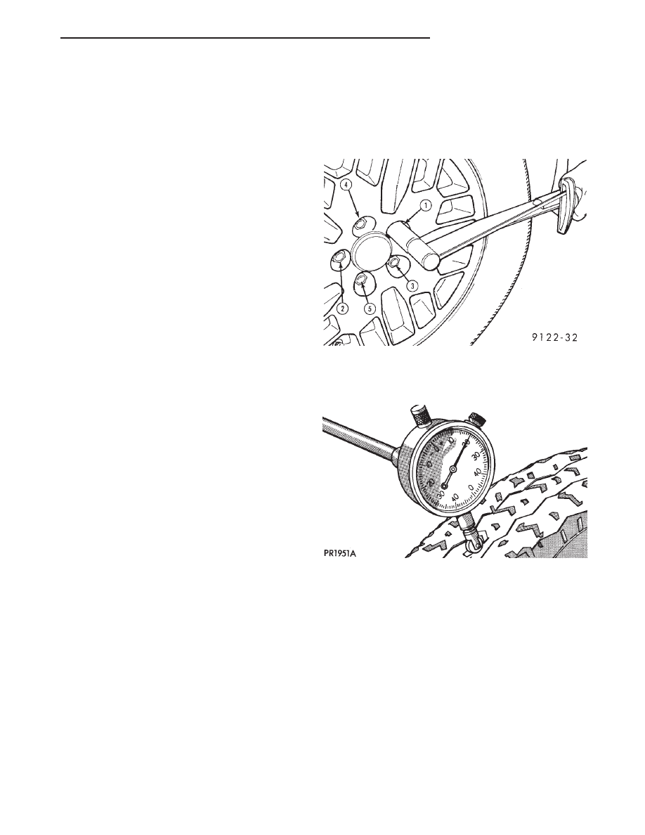
Verify all wheel nuts are properly torqued (Fig. 2).
Use run out gauge D-128-TR to determine run out
(Fig. 3).
Relocate the wheel on the mounting studs, two
studs over from the original position.
Retighten
wheel
nuts
until
all
are
properly
torqued. This will prevent brake distortion.
Check radial run out. If still excessive, mark tire
sidewall, wheel, and stud at point of maximum run
out (Fig. 4) and proceed to Method 2.
METHOD 2 (RELOCATE TIRE ON WHEEL)
Rotating tire on wheel is particularly effective
when there is run out in both tire and wheel.
Remove tire from wheel and remount wheel on hub
in former position.
Check wheel radial run out (Fig. 5). It should be no
more than 0.762 mm (0.030 inch).
Fig. 2 Tightening Wheel Nuts
Fig. 3 Run Out Gauge
JX
TIRES AND WHEELS
22 - 9
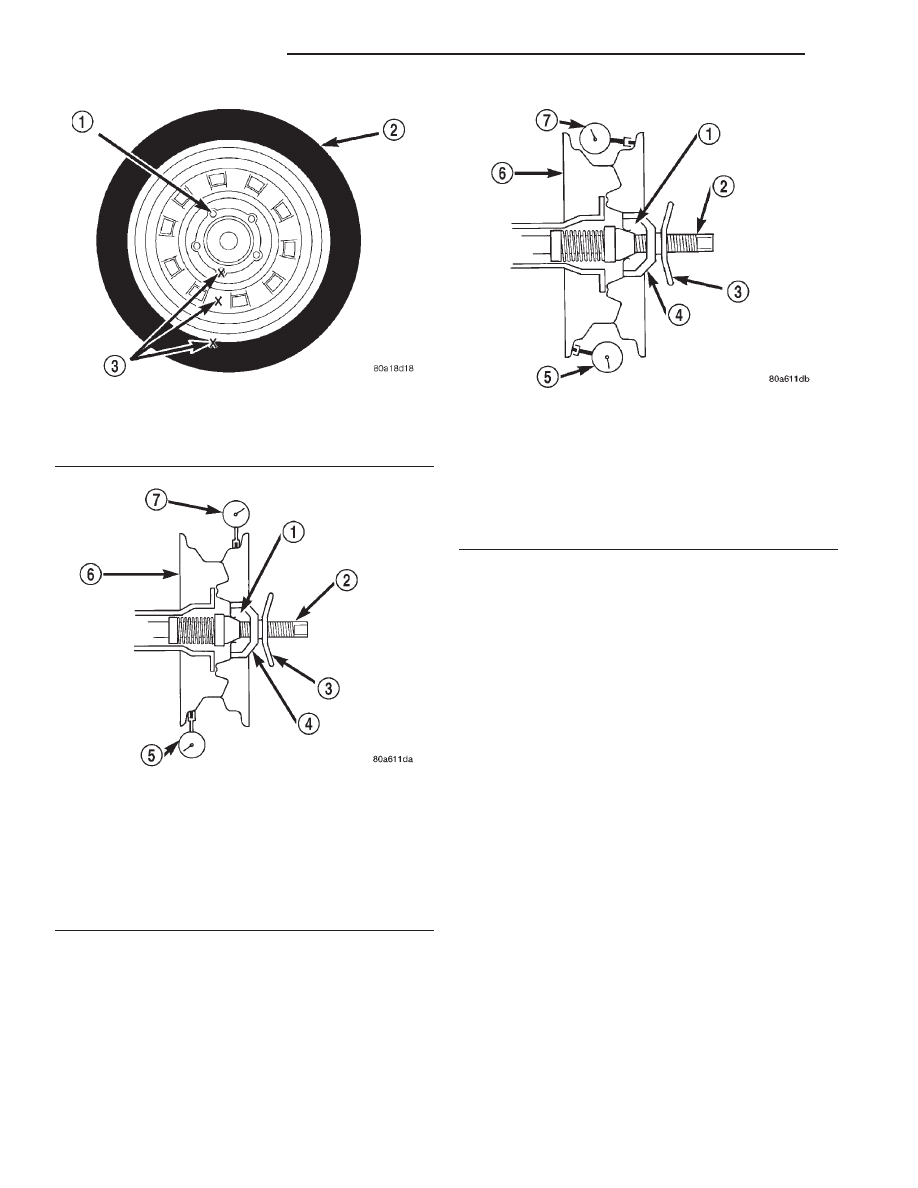
Check wheel lateral run out (Fig. 6). It should be
no more than 0.762 mm (0.030 inch).
If the point of greatest wheel radial run out is near
the original chalk mark, remount the tire on the rim
180 degrees from its original position. Recheck the
run out. If this does not reduce the run out to an
acceptable level, replace the wheel and/or the tire.
SERVICE PROCEDURES
TIRE AND WHEEL BALANCE
Balancing need is indicated by vibration of seats,
floor pan, or steering wheel. The vibration will be
noticed mostly when driving over 90 km/h (55 mph)
on a smooth road.
It is recommended that a two plane dynamic bal-
ancer be used when a wheel and tire assembly
require balancing. Static balancing should be used
only when a two plane balancer is not available.
Off-vehicle tire and wheel balancing is recom-
mended to be used on this vehicle.
NOTE: If on vehicle equipment is being used to bal-
ance the tire /wheel assemblies, remove the oppo-
site tire/wheel from the vehicle.
For static balancing, find the location of heavy spot
on tire/wheel causing the imbalance. Counter balance
wheel directly opposite the heavy spot. Determine
weight required to counterbalance the area of imbal-
ance. Place half of this weight on the inner rim
flange and the other half on the outer rim flange
(Fig. 7).
For dynamic balancing, the balancing equipment is
designed to indicate the location and amount of
weight to be applied to both the inner and outer rim
flanges (Fig. 8)
Fig. 4 Chalk Marking On Wheel, Tire And Stud
1 – STUD
2 – TIRE
3 – CHALK MARK LOCATIONS
Fig. 5 Checking Wheel Radial Run Out
1 – MOUNTING CONE
2 – SPINDLE SHAFT
3 – WING NUT
4 – PLASTIC CUP
5 – DIAL INDICATOR
6 – WHEEL
7 – DIAL INDICATOR
Fig. 6 Checking Wheel Lateral Run Out
1 – MOUNTING CONE
2 – SPINDLE SHAFT
3 – WING NUT
4 – PLASTIC CUP
5 – DIAL INDICATOR
6 – WHEEL
7 – DIAL INDICATOR
22 - 10
TIRES AND WHEELS
JX
DIAGNOSIS AND TESTING (Continued)
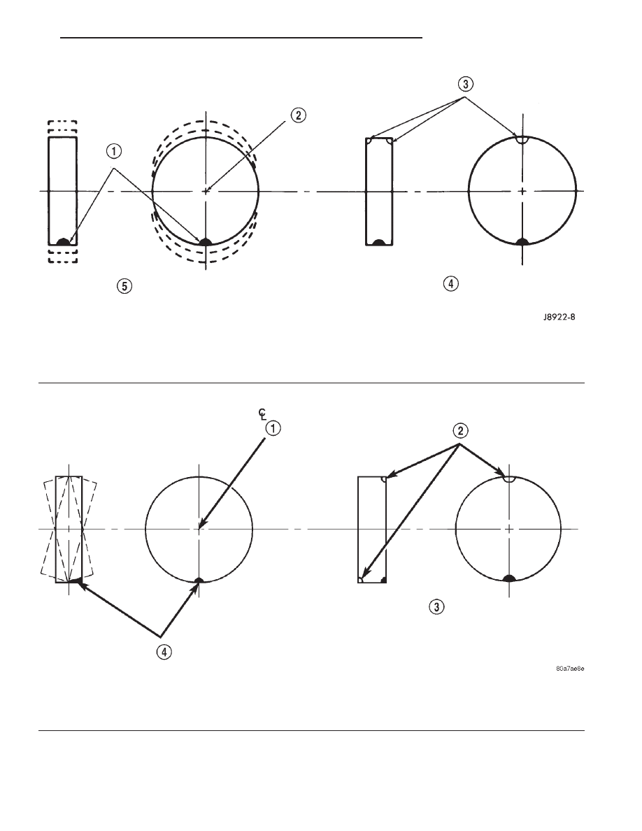
Fig. 7 Static Unbalance & Balance
1 – HEAVY SPOT
2 – OF SPINDLE
3 – ADD BALANCE WEIGHTS HERE
4 – CORRECTIVE WEIGHT LOCATION
5 – TIRE OR WHEEL TRAMP, OR WHEEL HOP
Fig. 8 Dynamic Unbalance & Balance
1 – OF SPINDLE
2 – ADD BALANCE WEIGHTS HERE PER DIRECTION OF
DYNAMIC BALANCING EQUIPMENT.
3 – CORRECTIVE WEIGHT LOCATION
4 – HEAVY SPOT WHEEL SHIMMY AND VIBRATION
JX
TIRES AND WHEELS
22 - 11
SERVICE PROCEDURES (Continued)
REMOVAL AND INSTALLATION
WHEEL AND TIRE
REMOVAL
(1) Raise the vehicle so the tires clear ground
level.
Refer
to
LUBRICATION
AND
MAINTE-
NANCE for the required procedure.
(2) If the vehicle is equipped with wheel covers,
remove the cover from the wheel by prying it off with
an appropriate wheel cover removal tool.
(3) Remove the wheel nuts from the studs.
(4) Remove the tire and wheel from the hub.
INSTALLATION
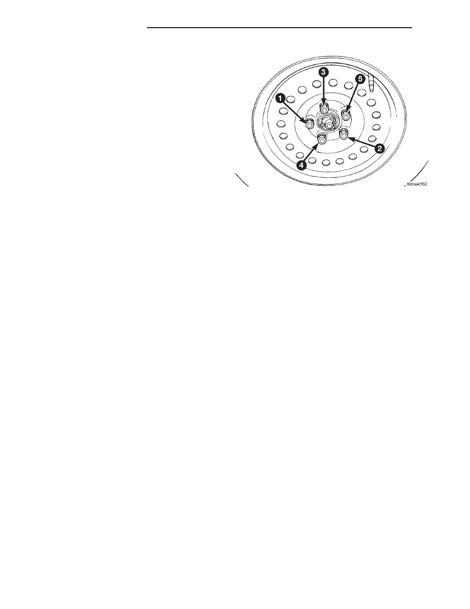
(1) To install the wheel, first position it properly
on the studs and hub mounting surface using the
hub pilot as a guide. Install and lightly tighten the
wheel nuts in the proper sequence (Fig. 9).
CAUTION: Never apply oil or grease to the wheel
mounting studs or nuts.
(2) Progressively tighten the 5 wheel nuts in the
proper sequence (Fig. 9) until tightened to half of the
specified torque. Then tighten the wheel nuts in the
proper sequence to a torque of 135 N·m (100 ft. lbs.).
(3) If equipped with wheel covers, align the valve
stem notch in the wheel cover with the valve stem on
the wheel. By hand, tap the wheel cover onto the
wheel until it is fully seated against the wheel.
(4) Lower the vehicle.
CLEANING AND INSPECTION
ALUMINUM WHEEL CARE
Chrome plated and painted aluminum wheels
should be cleaned regularly using mild soap and
water to maintain their luster and to prevent corro-
sion.
Care must be taken in the selection of tire and
wheel cleaning chemicals and equipment to prevent
damage to the wheels. Any of the “DO NOT USE”
items listed below WILL damage chrome plated and
painted aluminum wheels.
DO NOT USE:
• any abrasive metal cleaner
• any abrasive cleaning pad or brush
• any cleaner that contains an acid (this will
immediately react with and discolor the chromium
surface)
• chrome polish (unless it is buffed off immedi-
ately after application)
• oven cleaner
• a car wash that uses carbide-tipped wheel clean-
ing brushes
SPECIFICATIONS
WHEEL SPECIFICATIONS
Wheel:
Mounting Stud Size . . . . . . . . . . . . M12 x 1.5mm
Mounting Stud Lug Nut Hex Size . . . . . . . 19mm
Mounting Lug Nut Tightening Torque . . 135 N·m
(100 ft. lbs.)
Fig. 9 Wheel Nut Tightening Sequence
22 - 12
TIRES AND WHEELS
JX
Нет комментариевНе стесняйтесь поделиться с нами вашим ценным мнением.
Текст