
Chrysler Stratus Convertible. Manual — part 74
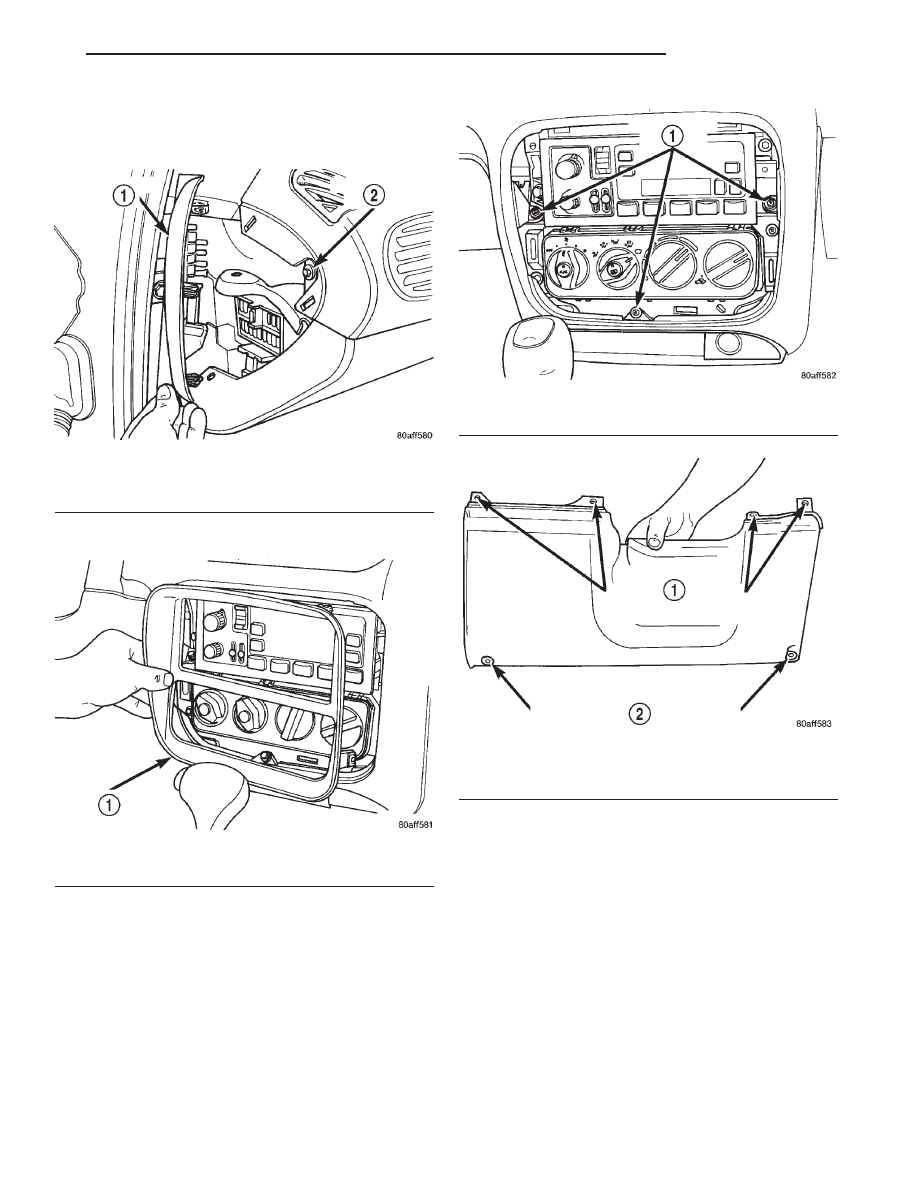
(6) Remove fuse panel cover from left end of
instrument panel. Remove screw holding end of
instrument panel top cover (Fig. 53).
(7) Pull center bezel off (Fig. 54).
(8) Remove screws holding instrument panel top
cover to center of instrument panel (Fig. 55).
(9) Pull instrument panel top cover up enough to
gain access to knee bolster screws (Fig. 56).
(10) Remove lower knee bolster screws and knee
bolster.
(11) Remove screws from lower steering column
shroud (Fig. 57).
(12) Pull lower shroud to clear ignition cylinder
(Fig. 58).
Fig. 53 Instrument Panel Top Cover–Left Side
1 – FUSE PANEL COVER
2 – TOP COVER SCREW
Fig. 54 Center Bezel
1 – CENTER BEZEL
Fig. 55 Instrument Panel Top Cover–Center
1 – TOP COVER SCREWS
Fig. 56 Knee Bolster Attaching Points
1 – KNEE BOLSTER SCREW LOCATIONS UNDER TOP COVER
2 – LOWER SCREW LOCATIONS
JX
TRANSAXLE
21 - 35
REMOVAL AND INSTALLATION (Continued)
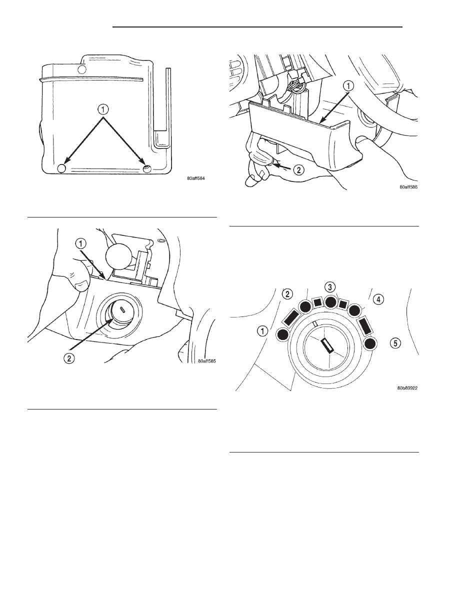
(13) Hold tilt wheel lever down and slide lower
shroud forward to remove it from column (Fig. 59).
(14) Tilt wheel to full down position and remove
upper steering column shroud.
(15) Disconnect interlock solenoid connector.
(16) Disconnect nylon cable retainer from lower
column mounting stud.
(17) Place the ignition key in the ON/RUN position
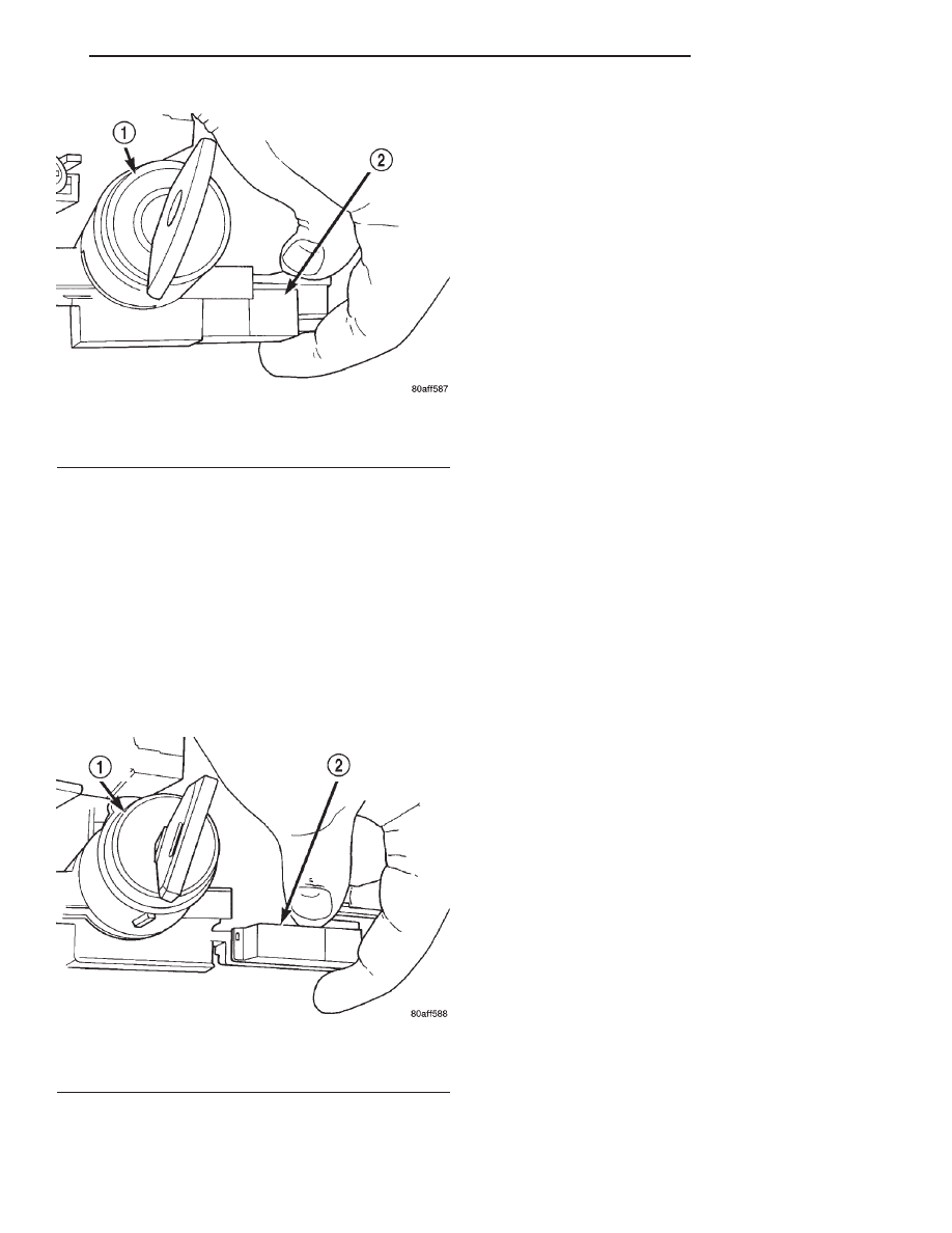
(Fig. 60). Grasp the interlock cable clip and connec-
tor. Remove the cable from the interlock housing
(Fig. 61).
(18) Remove interlock cable from underside of
instrument panel.
Fig. 57 Lower Steering Column Shroud Screw
Locations
1 – LOWER STEERING COLUMN SHROUD SCREW LOCATIONS
Fig. 58 Remove Lower Shroud From Ignition
Cylinder
1 – LOWER SHROUD
2 – KEY CYLINDER
Fig. 59 Lower Shroud Removal
1 – LOWER SHROUD
2 – TILT LEVER
Fig. 60 Ignition Key/Switch Positions
1 – ACC
2 – LOCK
3 – OFF
4 – ON/RUN
5 – START
21 - 36
TRANSAXLE
JX
REMOVAL AND INSTALLATION (Continued)
INSTALLATION
CAUTION: When installing interlock cable assem-
bly, care must be taken not to bend exposed cable
wire and slug at shifter end of cable.
(1) Route interlock cable into lower dash panel and
towards console as removed.
(2) Turn the ignition switch to the ON/RUN posi-
tion (Fig. 60).
(3) Install the interlock cable into the interlock
housing at the steering column (Fig. 62). Verify the
cable snaps into the housing.
(4) Install nylon cable retainer to lower column
mounting stud.
(5) Connect solenoid connector.
(6) Insert interlock cable core wire into interlock
adjustment lever groove. Make sure the interlock
cable slug is seated in the groove (Fig. 52).
(7) Insert interlock cable adjuster end into bracket
and snap into place (Fig. 52).
NOTE: The Interlock Cable MUST be adjusted.
Refer to Interlock System Adjustment, in this group.
CAUTION: When installing forward console, the
console will contact nylon shift release plunger
(Fig. 50). If care is not used, plunger may break,
requiring shifter assembly replacement.
(8) Install the forward IP console (front). Refer to
Group 23, Body for the proper procedures.
(9) Install the floor console (rear). Refer to Group
23, Body for the proper procedures.
(10) Install the gearshift knob and tighten set
screw (Fig. 49) to 2 N·m (20 in.lbs.).
(11) Tilt wheel to full down position and install
upper steering column shroud.
(12) Hold tilt wheel lever down and slide lower
shroud in at column.
(13) Install
screws
at
lower
steering
column
shroud.
(14) Install lower knee bolster screws and knee
bolster.
(15) Install screws holding instrument panel top
cover to center of instrument panel.
(16) Install center bezel.
(17) Install screw holding end of instrument panel
top cover. Install fuse panel cover from left end of
instrument panel.
(18) Connect the battery negative cable.
INTERLOCK MECHANISM
REMOVAL
(1) Remove the lower column covers, knee bolster
and shrouds. Refer to Interlock Cable Replacement.
(2) Grasp the interlock cable and connector firmly.
Remove the interlock cable.
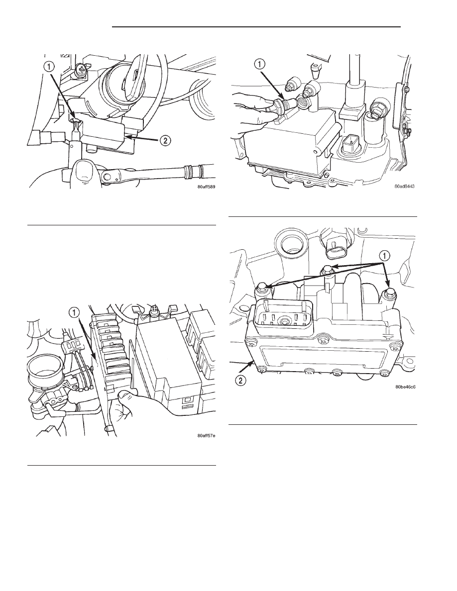
(3) Remove the two interlock mechanism to steer-
ing column attaching screws (Fig. 63). Remove the
interlock housing.
INSTALLATION
(1) Position the interlock housing at steering col-
umn. Install the two interlock mechanism to steering
column attaching screws. Torque screws to 3 N·m (21
in. lbs.).
(2) Snap the interlock cable into the housing.
(3) Install the lower column covers, shrouds and
knee bolster. Refer to Interlock Cable Replacement.
Fig. 61 Interlock Cable and Connector
1 – IGNITION LOCK CYLINDER
2 – INTERLOCK CABLE
Fig. 62 Interlock Cable At Housing
1 – IGNITION SWITCH
2 – INTERLOCK CABLE
JX
TRANSAXLE
21 - 37
REMOVAL AND INSTALLATION (Continued)
SOLENOID/PRESSURE SWITCH ASSEMBLY
REMOVAL
(1) Disconnect battery negative cable.
(2) Remove air cleaner assembly.
(3) Remove
the
Transmission
Control
module
(TCM) (Fig. 64).
(4) Disconnect and remove the input speed sensor
(Fig. 65).
(5) Disconnect the transmission oil cooler lines.
Cap off hoses and fittings to prevent foreign matter
intrusion.
(6) Disconnect the solenoid/pressure switch assem-
bly connector.
(7) Remove
the
three
solenoid/pressure
switch
assembly-to-transaxle case bolts (Fig. 66).
(8) Remove solenoid/pressure switch assembly and
gasket (Fig. 67).
CAUTION: Be sure to keep foreign material from
entering ports in transaxle case. Erratic transaxle
operation and/or failure can result.
INSTALLATION
(1) Install solenoid/pressure switch assembly to
case using a new gasket (Fig. 67).
(2) Install bolts and torque to 13 N·m (110 in. lbs.)
(Fig. 66).
Fig. 63 Interlock Mechanism
1 – MOUNTING SCREW
2 – INTERLOCK MECHANISM
Fig. 64 Transmission Control Module (TCM)
1 – TRANSMISSION CONTROL MODULE
Fig. 65 Input Speed Sensor
1 – INPUT (TURBINE) SPEED SENSOR
Fig. 66 Attaching Bolts
1 – BOLTS
2 – SOLENOID AND PRESSURE SWITCH ASSEMBLY
21 - 38
TRANSAXLE
JX
REMOVAL AND INSTALLATION (Continued)
Нет комментариевНе стесняйтесь поделиться с нами вашим ценным мнением.
Текст