
Chrysler Stratus Convertible. Manual — part 72
(8) Recheck the fluid level after the transaxle has
reached normal operating temperature (180°F.). Refer
to Fluid Level and Condition Check in this group for
the proper fluid fill procedure.
(9) To prevent dirt from entering transaxle, make
certain that dipstick is fully seated into the dipstick
opening.
ALTERNATIVE MAINTENANCE METHODS
TRANSAXLE FLUID EXCHANGER METHOD
CAUTION: The use of any fluid exchanger that
introduces additives into the transaxle is not rec-
ommended.
(1) To perform the transaxle fluid exchange, the
transaxle must be at operating temperature. Drive
the vehicle until it reaches full operating tempera-
ture.
(2) Obtain a suitable transaxle fluid exchanger
and verify the tank is clean and dry.
(3) Fill the tank to the recommended fill capacity
with Mopar
t ATF+4 Type 9602.
(4) Connect the machine to the vehicle following
the
manufacturers
instructions.
Perform
the
exchange procedure following the instructions pro-
vided with the machine.
(5) Once
machine
has
completed
the
fluid
exchange. Check the fluid level and condition and fill
to proper level with Mopar
t ATF+4 Type 9602. Refer
to Fluid Level and Condition Check in this group for
the proper fluid fill procedure.
NOTE: Verify that the transaxle cooler lines are
tightened
to
proper
specifications.
Cooler
line
torque specification is 2 N
•
m (18 in. lbs.).
DIPSTICK TUBE FLUID SUCTION METHOD
(1) When performing the fluid suction method,
make sure the transaxle is at full operating temper-
ature.
(2) To perform the dipstick tube fluid suction
method, use a suitable fluid suction device (Vacula
y
or equivalent).
(3) Insert the fluid suction line into the dipstick
tube.
NOTE: Verify that the suction line is inserted to the
lowest point of the transaxle oil pan. This will
ensure complete evacuation of the fluid in the pan.
(4) Follow the manufacturers recommended proce-
dure and evacuate the fluid from the transaxle.
(5) Remove the suction line from the dipstick tube.
(6) Pour four quarts of Mopar
t ATF+4 (Automatic
Transmission Fluid) Type 9602 through the dipstick
opening.
(7) Start engine and allow to idle for at least one
minute. Then, with parking and service brakes
applied, move selector lever momentarily to each
position, ending in the park or neutral position.
(8) Check the transaxle fluid level and add an
appropriate amount to bring the transaxle fluid level
to 3mm (1/8 in.) below the “ADD” mark on the dip-
stick (Fig. 34).
(9) Recheck the fluid level after the transaxle has
reached normal operating temperature (180°F.). Refer
to Fluid Level and Condition Check in this group for
the proper fluid fill procedure.
(10) To prevent dirt from entering transaxle, make
certain that dipstick is fully seated into the dipstick
opening.
ALUMINUM THREAD REPAIR
Damaged or worn threads in the aluminum tran-
saxle case and valve body can be repaired by the use
of Heli-Coils, or equivalent. This repair consists of
drilling out the worn-out damaged threads. Then tap
the hole with a special Heli-Coil tap, or equivalent,
and installing a Heli-Coil insert, or equivalent, into
the hole. This brings the hole back to its original
thread size.
Heli-Coil, or equivalent, tools and inserts are
readily available from most automotive parts suppli-
ers.
FLUSHING COOLERS AND TUBES
When a transaxle failure has contaminated the
fluid, the oil cooler(s) must be flushed. The cooler
bypass valve in the transaxle must be replaced also.
The torque converter must also be replaced with an
exchange unit. This will insure that metal particles
or sludged oil are not later transferred back into the
reconditioned (or replaced) transaxle.
The recommended procedure for cooler flushing is
to use Tool 6906 Cooler Flusher.
JX
TRANSAXLE
21 - 27
SERVICE PROCEDURES (Continued)
WARNING: WEAR PROTECTIVE EYEWEAR THAT
MEETS THE REQUIREMENTS OF OSHA AND ANSI
Z87.1–1968. WEAR STANDARD INDUSTRIAL RUB-
BER GLOVES.
KEEP LIGHTED CIGARETTES, SPARKS, FLAMES,
AND OTHER IGNITION SOURCES AWAY FROM THE
AREA TO PREVENT THE IGNITION OF COMBUSTI-
BLE LIQUIDS AND GASES. KEEP A CLASS (B) FIRE
EXTINGUISHER
IN
THE
AREA
WHERE
THE
FLUSHER WILL BE USED.
KEEP THE AREA WELL VENTILATED.
DO NOT LET FLUSHING SOLVENT COME IN CON-
TACT WITH YOUR EYES OR SKIN: IF EYE CONTAM-
INATION OCCURS, FLUSH EYES WITH WATER FOR
15 TO 20 SECONDS. REMOVE CONTAMINATED
CLOTHING AND WASH AFFECTED SKIN WITH
SOAP AND WATER. SEEK MEDICAL ATTENTION.
(1) Remove cover plate filler plug on Tool 6906.
Fill reservoir 1/2 to 3/4 full of fresh flushing solution.
Flushing solvents are petroleum based solutions gen-
erally used to clean automatic transmission compo-
nents. DO NOT use solvents containing acids, water,
gasoline, or any other corrosive liquids.
(2) Reinstall filler plug on Tool 6906.
(3) Verify pump power switch is turned OFF. Con-
nect red alligator clip to positive (+) battery post.
Connect black (-) alligator clip to a good ground.
NOTE: When
flushing
transmission
cooler
and
lines, ALWAYS reverse flush.
(4) Connect the BLUE pressure line to the OUT-
LET (From) cooler line.
(5) Connect the CLEAR return line to the INLET
(To) cooler line
(6) Turn pump ON for two to three minutes to
flush cooler and lines.
(7) Turn pump OFF.
(8) Disconnect CLEAR suction line from reservoir
at cover plate. Disconnect CLEAR return line at
cover plate, and place it in a drain pan.
(9) Turn pump ON for 30 seconds to purge flush-
ing solution from cooler and lines. Turn pump OFF.
(10) Place CLEAR suction line into a one quart
container of Mopar
t ATF+4 (Automatic Transmission
Fluid—Type 9602).
(11) Turn pump ON until all transmission fluid is
removed from the one quart container and lines. This
purges any residual cleaning solvent from the trans-
mission cooler and lines. Turn pump OFF.
(12) Disconnect alligator clips from battery. Recon-
nect flusher lines to cover plate, and remove flushing
adapters from cooler lines.
OIL PUMP VOLUME CHECK
Measuring oil pump output volume will determine
if sufficient flow to the transmission oil cooler exists,
and whether or not an internal transmission failure
is present.
Verify that transmission fluid is at the proper
level. Refer to Fluid Level and Condition in this
Group. If adding fluid is necessary, fill to the proper
level with Mopar
t ATF+4 (Automatic Transmission
Fluid–Type 9602). The following procedure is to
check oil pump output volume:
(1) Disconnect the To cooler line at the oil cooler
inlet and place a collecting container under the dis-
connected line.
CAUTION: With the fluid set at the proper level,
fluid collection should not exceed (1) quart or inter-
nal damage to the transmission may occur.
(2) Start engine and run at curb idle speed, with
the shift selector in neutral.
(3) If one quart of ATF is collected in 20 seconds or
less, flow is within acceptable limits. If fluid flow is
intermittent or it takes more than 20 seconds to col-
lect one quart of ATF, refer to Hydraulic Pressure
Tests in this Group.
(4) Inspect the cooler hose for damage. Replace if
necessary.
(5) Connect the To cooler hose to the oil cooler
inlet and torque clamp to 2 N·m (20 in. lbs.) torque.
(6) Refill
the
transaxle
to
proper
level
with
Mopar
t ATF+4 (Automatic Transmission Fluid–Type
9602).
TRANSAXLE QUICK LEARN PROCEDURE
The quick learn procedure requires the use of the
DRB scan tool.
This program allows the electronic transaxle sys-
tem to recalibrate itself. This will provide the best
possible transaxle operation. The quick learn proce-
dure should be performed if any of the following pro-
cedures are performed:
• Transaxle Assembly Replacement
• Transmission Control Module Replacement
• Solenoid/Pressure Switch Assembly Replacement
• Clutch Plate and/or Seal Replacement
• Valve Body Replacement or Recondition
To perform the Quick Learn Procedure, the follow-
ing conditions must be met:
• The brakes must be applied
• The engine speed must be above 500 rpm
• The throttle angle (TPS) must be less than 3
degrees
• The shift lever position must stay until
prompted to shift to overdrive
21 - 28
TRANSAXLE
JX
SERVICE PROCEDURES (Continued)
• The shift lever position must stay in overdrive
after the Shift to Overdrive prompt until the DRB
indicates the procedure is complete
• The calculated oil temperature must be above
60° and below 200°
(1) Plug the DRB scan tool into the data link con-
nector. The connector is located under the instrument
panel.
(2) Go to the Transmission screen.
(3) Go to the Miscellaneous screen.
(4) Select Quick Learn Procedure. Follow the
instructions of the DRB to perform the Quick Learn
Procedure.
PINION FACTOR PROCEDURE
The vehicle speed readings for the speedometer are
taken from the output speed sensor. The TCM must
be calibrated to the different combinations of equip-
ment available. Pinion Factor allows the technician
to set the Transmission Control Module initial set-
ting so that the speedometer readings will be correct.
Failure to perform this procedure will cause a No
Speedometer Operation condition.
This procedure must be performed if the Transmis-
sion Control Module has been replaced.
To properly read or reset the Pinion Factor, it is
necessary to use a DRB scan tool. Perform the follow-
ing steps with the DRB scan tool to read or reset the
Pinion Factor:
(1) Plug the DRB scan tool into the data link con-
nector located under the instrument panel.
(2) Select the Transmission menu.
(3) Select the Miscellaneous menu.
(4) Select Pinion Factor. Then follow the instruc-
tions on the DRB scan tool screen.
REMOVAL AND INSTALLATION
GEARSHIFT CABLE
REMOVAL
(1) Place transaxle in PARK.
(2) Disconnect battery negative cable at left strut
tower.
(3) Remove air cleaner assembly.
(4) Disconnect battery positive cable.
(5) Disconnect
Transmission
Control
Module
(TCM) connector. Remove TCM.
(6) Pull Power Distribution Center (PDC) up and
out of the way.
(7) Using a pry tool, pry up on cable at manual
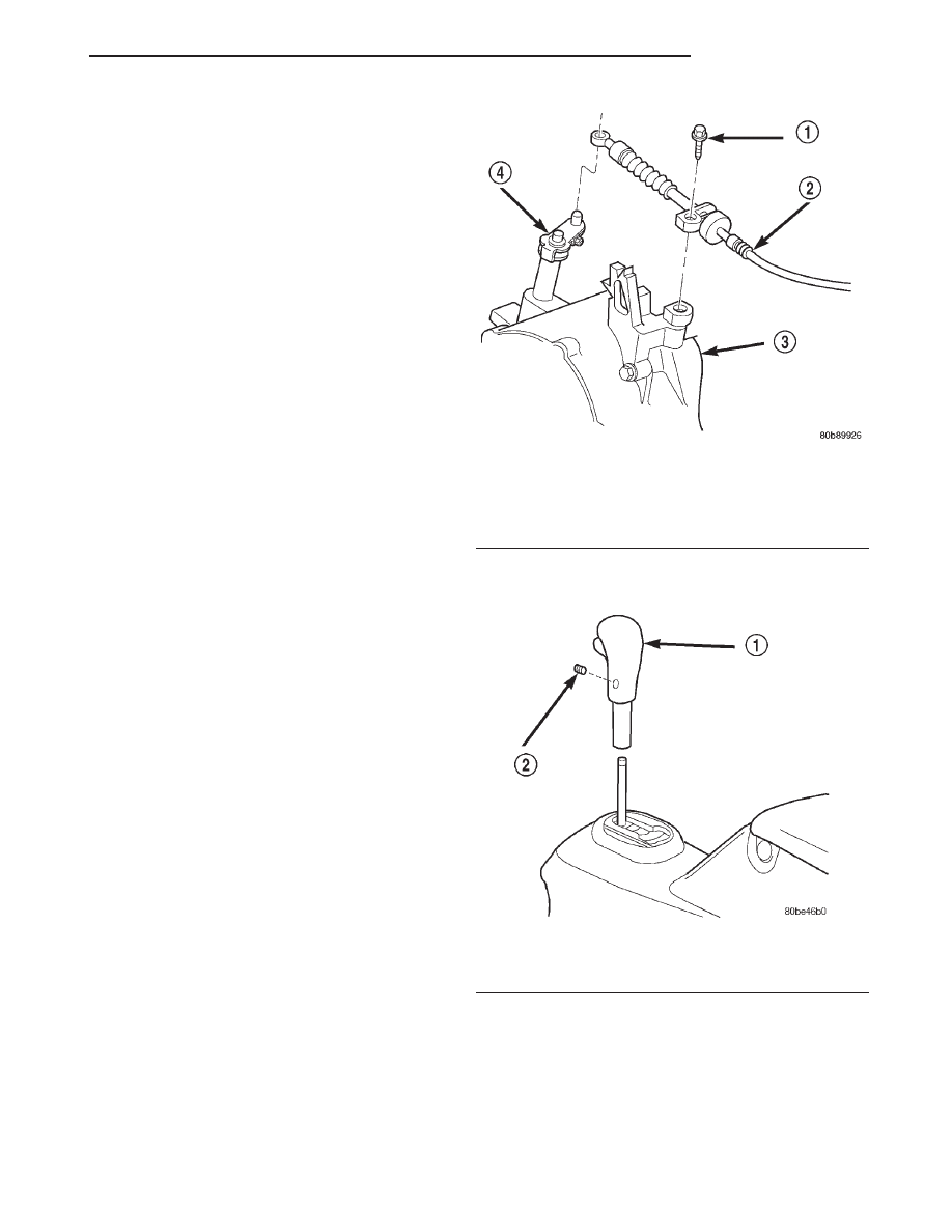
valve lever and remove cable from lever (Fig. 35).
(8) Remove the screw from the cable bracket at the
transaxle (Fig. 35).
(9) Remove the gearshift knob set screw and knob
(Fig. 36).
(10) Remove the floor console (rear). Refer to
Group 23, Body for the proper procedures.
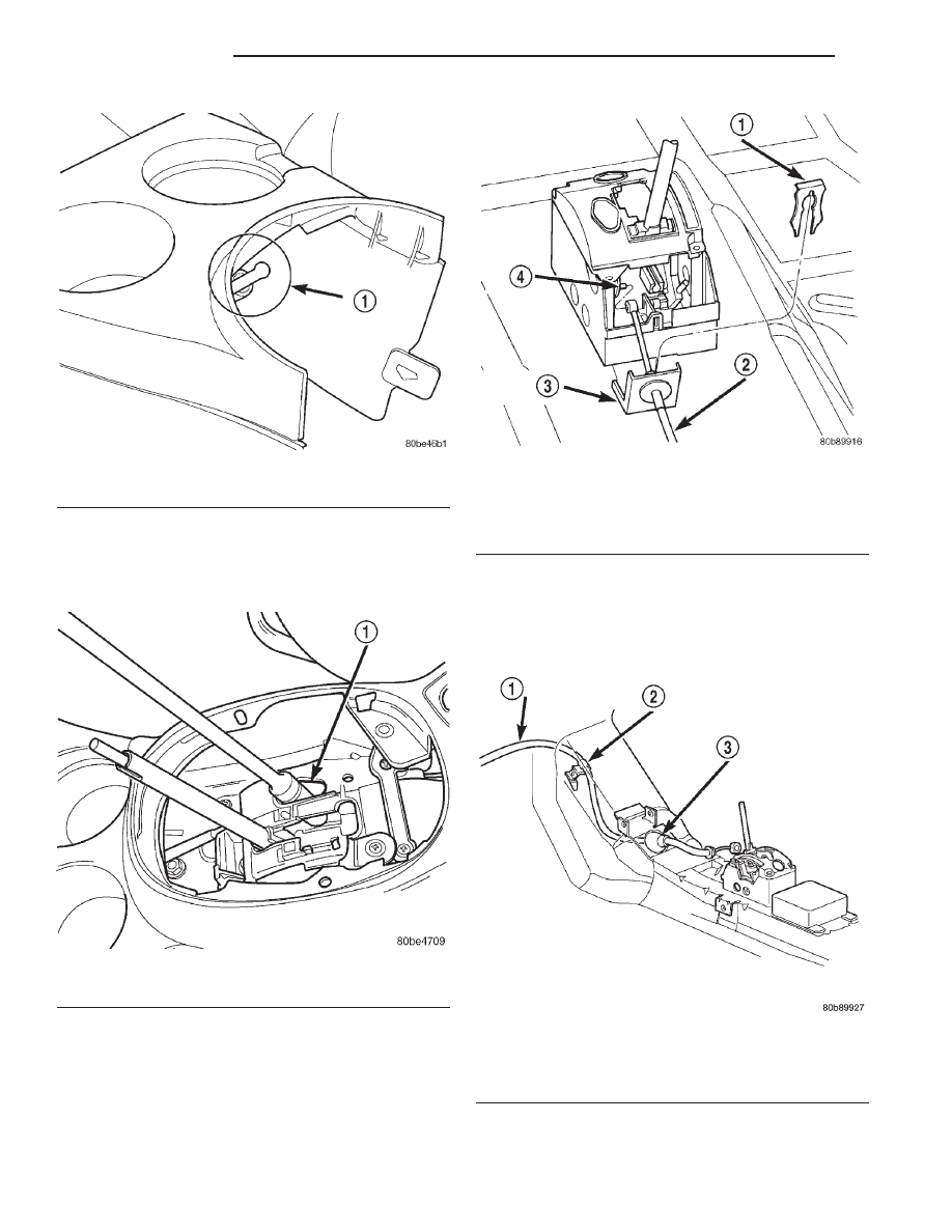
CAUTION: When removing forward console, the
console will contact nylon shift release plunger
(Fig. 37). If care is not used, plunger may break,
requiring shifter assembly replacement.
Fig. 35 Gearshift Cable at Transaxle
1 – SCREW
2 – CABLE
3 – TRANSAXLE
4 – SHIFT LEVER
Fig. 36 Shifter Knob Removal/Installation
1 – SHIFTER KNOB
2 – SET SCREW
JX
TRANSAXLE
21 - 29
SERVICE PROCEDURES (Continued)
(11) Remove the forward IP console (front). Refer
to Group 23, Body for the proper procedures.
(12) Loosen nut on shift cable adjust lever (Fig.
38).
(13) Using a flat blade pry tool, remove the shifter
cable core end from the shift lever pin (Fig. 39).
(14) Using a flat blade pry tool, pry the cable con-
duit clip up from the shifter bracket. Pull up on the
cable conduit and remove from bracket (Fig. 39).
(15) Hoist vehicle. Refer to Group 0, Lubrication
and Maintenance.
(16) Remove the cable grommet from the floor pan
area (Fig. 40).
(17) Carefully remove the cable from the under-
body by unfolding the cable retainer clip (Fig. 40) as
you go along.
Fig. 37 Console/Shifter Contact Area
1 – AREA OF CONTACT
Fig. 38 Shift Cable Adjust Lever Nut
1 – ACCESS HOLE
Fig. 39 Gearshift Cable at Floor Shifter—Typical
1 – CLIP
2 – CABLE
3 – CONDUIT BRACKET
4 – SHIFT PIN
Fig. 40 Gearshift Cable Routing
1 – CABLE
2 – RETAINER CLIP
3 – GROMMET
21 - 30
TRANSAXLE
JX
REMOVAL AND INSTALLATION (Continued)
Нет комментариевНе стесняйтесь поделиться с нами вашим ценным мнением.
Текст