
Chrysler Stratus Convertible. Manual — part 132
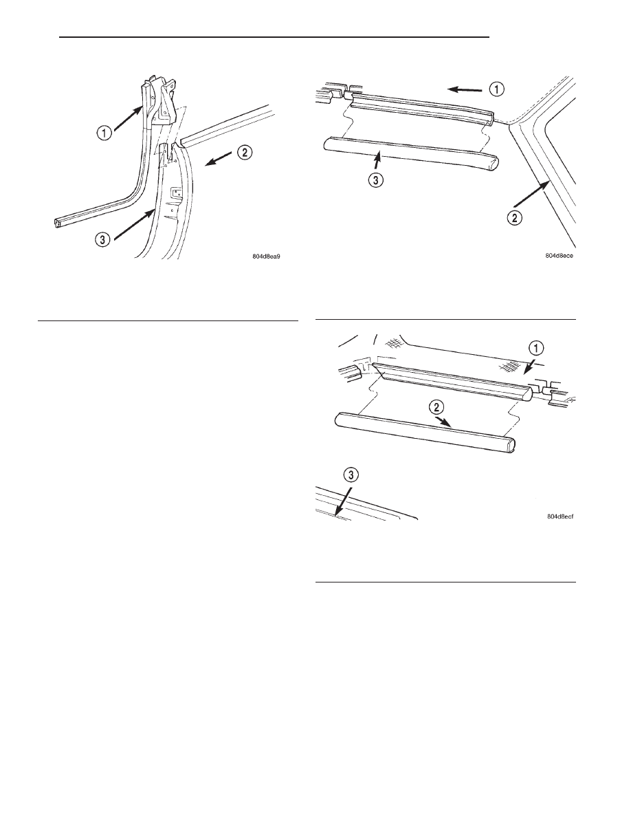
INSTALLATION
(1) Position panel weatherstrip onto vehicle.
(2) Install weatherstrip to door opening flange.
(3) Install push in fasteners attaching weather-
strip to B-pillar.
(4) Install door sill trim panel.
SIDE RAIL WEATHERSTRIPS
FRONT
REMOVAL
(1) Partially raise convertible top.
(2) Remove push in fasteners attaching weather-
strip to retainer.
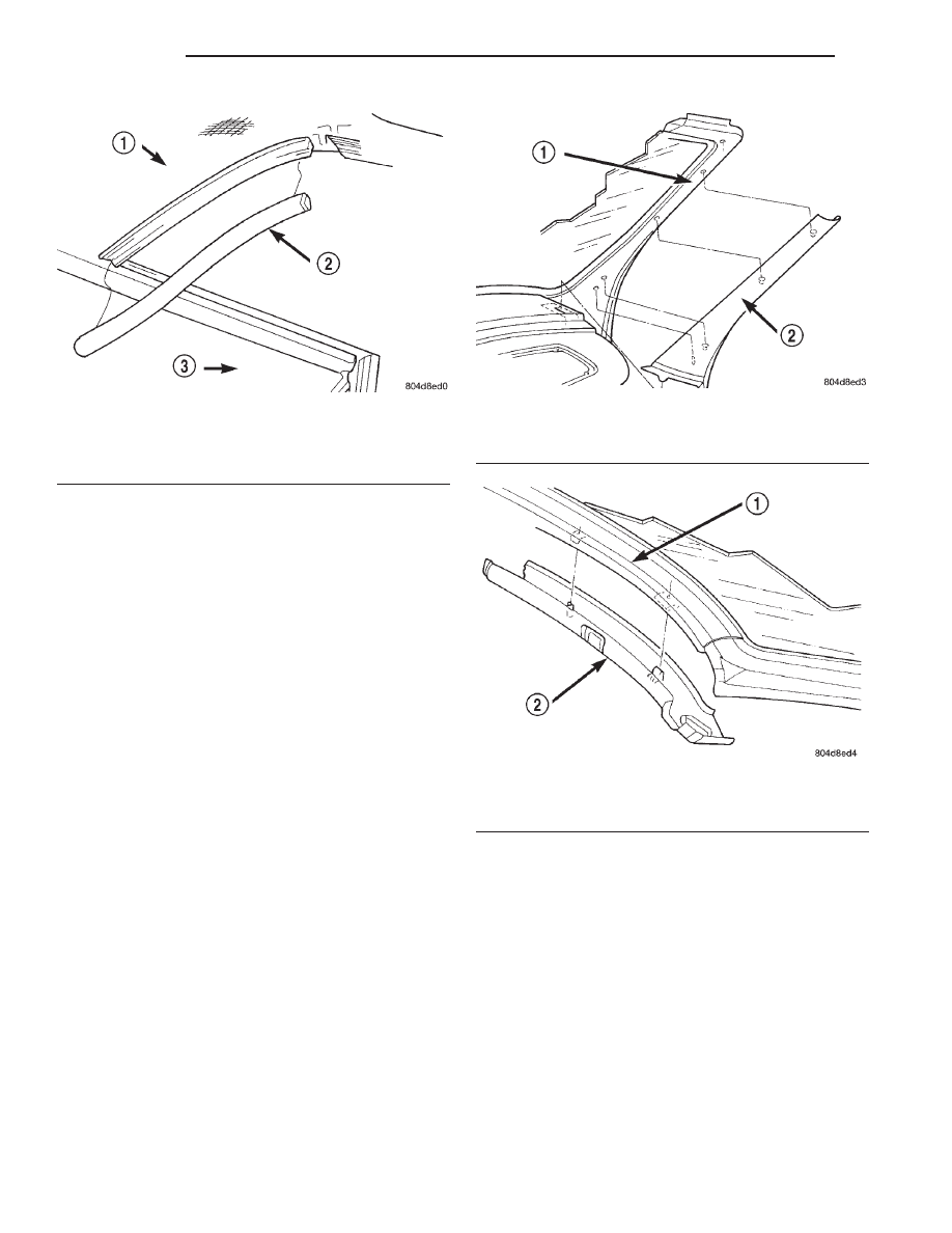
(3) Remove weatherstrip from vehicle (Fig. 64).
INSTALLATION
(1) Position weatherstrip on vehicle.
(2) Install push in fasteners into retainer channel,
aligning embossment on back side of weatherstrip to
corner of retainer.
(3) Lower convertible top.
(4) Secure convertible top.
CENTER
REMOVAL
(1) Partially raise convertible top.
(2) Remove push in fasteners attaching weather-
strip to retainer.
(3) Remove weatherstrip from vehicle (Fig. 65).
INSTALLATION
(1) Position weatherstrip on vehicle.
(2) Install push in fasteners into retainer channel,
aligning embossment on back side of weatherstrip to
corner of retainer.
(3) Lower convertible top.
(4) Secure convertible top.
REAR
REMOVAL
(1) Partially raise convertible top.
(2) Remove push in fasteners attaching weather-
strip to retainer.
(3) Separate weatherstrip from vehicle (Fig. 66).
Fig. 63 Quarter Panel Weatherstrip
1 – QUARTER PANEL WEATHERSTRIP
2 – QUARTER PANEL
3 – DOOR OPENING FLANGE
Fig. 64 Front Side Rail Weatherstrip
1 – CONVERTIBLE TOP
2 – A-PILLAR
3 – FRONT SIDE RAIL WEATHERSTRIP
Fig. 65 Center Side Rail Weatherstrip
1 – CONVERTIBLE TOP
2 – CENTER SIDE RAIL WEATHERSTRIP
3 – QUARTER PANEL
JX
BODY
23 - 61
REMOVAL AND INSTALLATION (Continued)
INSTALLATION
(1) Position weatherstrip on vehicle.
(2) Install push in fasteners into retainer channel,
aligning embossment on back side of weatherstrip to
corner of retainer.
(3) Push weatherstrip into retainer channel, align-
ing embossment on backside of weatherstrip to cor-
ner of retainer.
(4) Lower convertible top.
(5) Secure convertible top.
A-PILLAR TRIM PANEL
REMOVAL
(1) Disengage clips attaching A-pillar trim panel to
A-pillar.
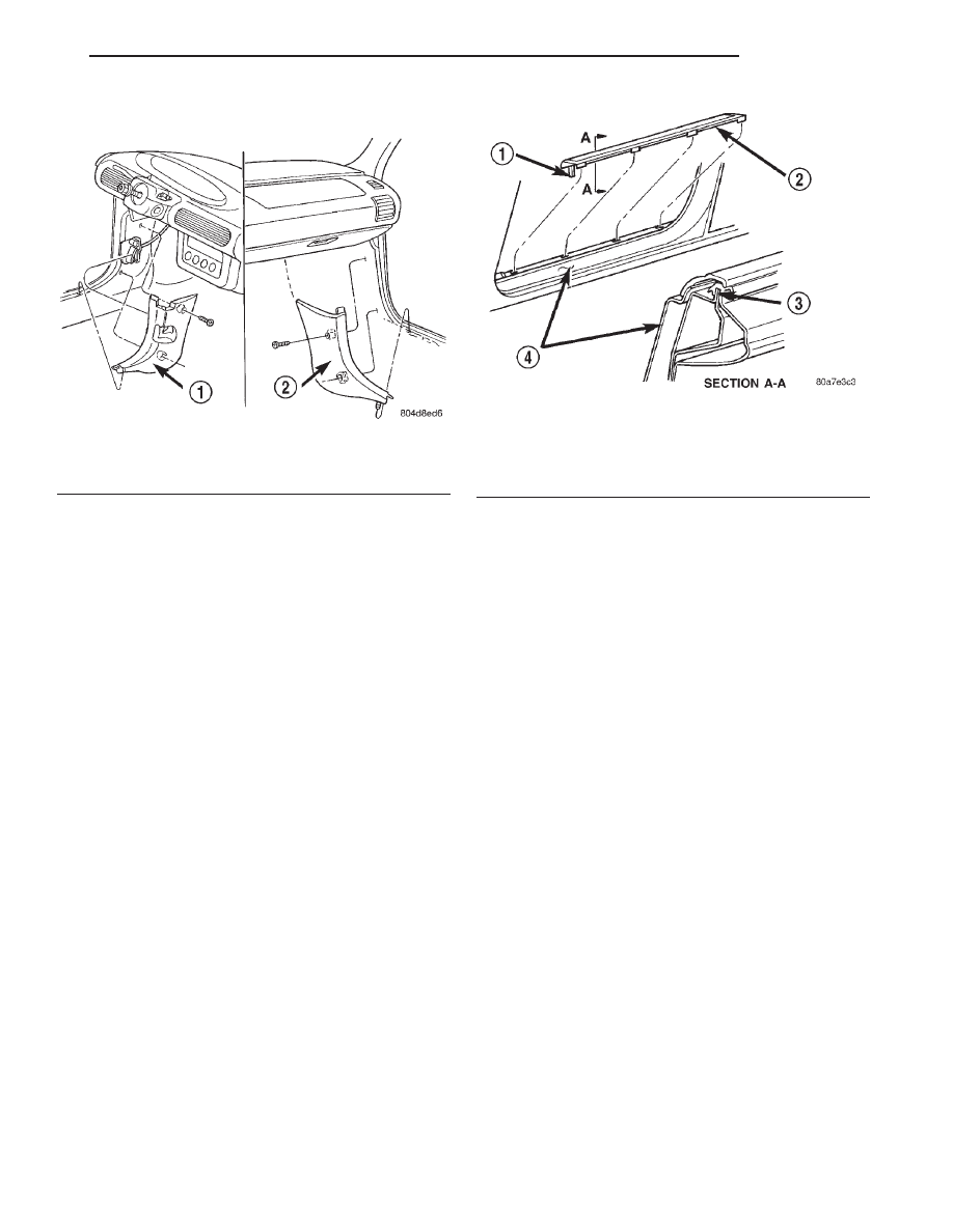
(2) Remove trim panel from vehicle (Fig. 67).
INSTALLATION
(1) Position trim panel near A-pillar.
(2) Align locating pins on back side of trim panel
to holes in A-pillar.
(3) Press clips on A-pillar trim panel into slots in
A-pillar.
HEADER TRIM PANEL – RIGHT OR LEFT
REMOVAL
(1) Remove sun visor.
(2) Remove inside rear view mirror, right side only.
(3) Disengage clip attaching header trim panel to
header panel.
(4) Remove header trim panel from vehicle (Fig.
68).
INSTALLATION
(1) Position header trim panel on vehicle.
(2) Align locating pins on back side of trim panel
to holes in header panel.
(3) Engage clip on trim panel to slots in header
panel.
(4) Install inside rear view mirror.
(5) Install sun visor.
COWL TRIM PANEL
REMOVAL
(1) Remove door sill trim panel.
(2) Remove screws attaching cowl trim panel to
inner cowl panel.
Fig. 66 Rear Side Rail Weatherstrip
1 – CONVERTIBLE TOP
2 – REAR SIDE RAIL WEATHERSTRIP
3 – QUARTER PANEL
Fig. 67 A-Pillar Trim Panel
1 – A-PILLAR
2 – A-PILLAR TRIM PANEL
Fig. 68 Header Trim Panel
1 – HEADER
2 – HEADER TRIM PANEL
23 - 62
BODY
JX
REMOVAL AND INSTALLATION (Continued)
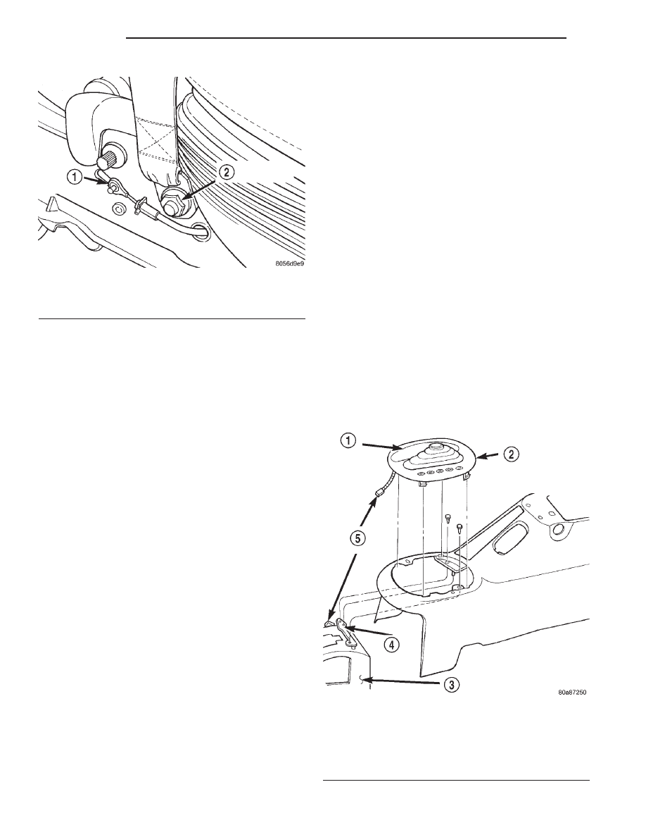
(3) Remove cowl trim panel from vehicle (Fig. 69).
INSTALLATION
(1) Position cowl trim panel to vehicle.
(2) Install screws attaching cowl trim panel to
inner cowl panel.
(3) Install door sill trim panel.
DOOR SILL TRIM PANEL
REMOVAL
(1) Using a fork type prying tool, disengage clips
holding door sill trim panel to door sill (Fig. 70).
(2) Starting at one end of sill trim panel, pull
upward on sill trim panel in order to disengage clips
attaching sill trim panel to door opening flange.
(3) Remove door sill trim panel from vehicle.
INSTALLATION
(1) Position door sill trim panel on vehicle.
(2) Align locating rib to net against cowl trim
panel.
(3) Engage clips on sill trim panel to door opening
flange.
NOTE: Check that header/A-pillar and quarter panel
weatherstrips are properly positioned. Incorrect
positioning will interfere with clip engagement to
door opening flange and damage door sill trim
panel.
(4) Engage clips attaching sill trim panel to door
sill.
FRONT SEAT BELT RETRACTOR
Inspect the condition of the shoulder belt and lap
belt. Replace any belt that is cut, frayed, torn, or
damaged in any way. Also, replace the shoulder belt
if the retractor is either damaged or inoperative.
REMOVAL
(1) Remove seat from vehicle.
NOTE: The torque prevailing nut used to secure the
lower seat belt anchor is not reusable. Verify avail-
ability prior to proceeding.
(2) Remove seat back cover to gain access to seat
belt retractor. Refer to procedure found in this sec-
tion.
(3) Remove seat belt retractor cover.
(4) Remove and discard bolts attaching seat belt
retractor to seat frame.
CAUTION: Do not reuse the bolts attaching the seat
belt retractor to the seat frame.
(5) Remove seat belt retractor from seat frame.
(6) Disconnect
wire
connector
from
seat
belt
retractor.
INSTALLATION
(1) Position seat belt retractor to seat frame.
(2) Connect wire connector to seat belt retractor.
(3) Install new bolts to hold seat belt retractor to
seat frame.
NOTE: The tighten the retractor bolts to 16.2 N·m
(12 ft. lbs.) torque.
(4) Install seat belt retractor cover.
(5) Install seat cover. Refer to procedure found in
this section.
Fig. 69 Cowl Trim Panel
1 – LEFT COWL TRIM PANEL
2 – RIGHT COWL TRIM PANEL
Fig. 70 Door Sill Trim Panel
1 – LOCATING TAB
2 – DOOR SILL TRIM PANEL
3 – DOOR OPENING FLANGE
4 – DOOR SILL
JX
BODY
23 - 63
REMOVAL AND INSTALLATION (Continued)
(6) Attach lower seat belt anchor to bolt on seat
adjuster.
(7) Verify that seat belt is routed such that it will
not be twisted when engaged to the seat belt buckle.
(8) Verify that a minimum of three threads extend
beyond the lower seat belt anchor nut and that the
lower seat belt anchor swivels freely. If both condi-
tions are not found, check that the bolt is fully
engaged to the seat adjuster.
(9) Install seat in vehicle.
CAUTION: Failure to follow proper installation pro-
cedure may result in the seat track latch pins not
being synchronized.
FRONT SEAT BELT BUCKLE
REMOVAL
NOTE: The torque prevailing nut holding the front
seat belt buckle to the seat adjuster is not reusable.
Verify availability prior to proceeding.
(1) Remove nut holding seat belt buckle to seat
adjuster. Discard nut.
(2) Remove seat belt buckle from seat.
INSTALLATION
(1) Verify that the black spacer washer is properly
installed over the shoulder of the weld nut on the
seat adjuster.
(2) Install seat belt buckle to bolt on seat adjuster.
(3) Verify that the seat belt buckle is sitting on the
shoulder of the weld nut on the seat adjuster.
(4) Install nut to hold seat belt buckle to seat
adjuster.
NOTE: The tighten the seat belt buckle nut is 45
N·m (33 ft. lbs.) torque.
(5) Verify that a minimum of three threads extend
beyond the seat belt buckle nut. If not, check that
the bolt is fully engaged to the seat adjuster.
FLOOR CONSOLE
REMOVAL
(1) Raise parking brake lever as high as possible.
(2) Move transmission shifter to neutral position.
(3) Loosen set screw on front of shifter knob and
remove shift lever knob.
(4) Remove lighted transmission range indicator
letter bezel (Fig. 72).
(5) Disconnect transmission range indicator bezel
wire connector at the shifter mechanism.
(6) Remove screws, next to floor shifter and in con-
sole storage compartment, attaching floor console to
brackets on floor pan.
(7) Disconnect wire connector for floor console
accessories at floor pan.
(8) Remove console from vehicle.
NOTE: The grip portion of the parking brake lever
will only fit through the wider lower portion of the
slot in the floor console.
Fig. 71 Lower Seat Belt Anchor And Recliner Cable
1 – RECLINER CABLE
2 – LOWER SEAT BELT ANCHOR
Fig. 72 Transmission Range Indicator Bezel
1 – BEZEL BOOT
2 – PRNDL BEZEL
3 – SHIFTER MECHANISM
4 – LOCATOR PIN
5 – WIRING CONNECTOR
23 - 64
BODY
JX
REMOVAL AND INSTALLATION (Continued)
Нет комментариевНе стесняйтесь поделиться с нами вашим ценным мнением.
Текст