Daewoo Matiz (2003 year). Manual — part 124

MANUAL TRANSAXLE DRIVE AXLE 3B – 11
D104B704
5. Remove the drive axle shaft boot.
D104B708
Assembly Procedure
1. Install in the reverse order of removal.
2. Install the joint assembly.
D
Pre–install the joint assembly by pushing to the
drive axle shaft to widen the circlip.
D
Keep the circlip widened (1).
D
Push the joint assembly to the drive axle shaft (2).
D104B709
3. Fill the joint housing with recommended grease when
installing.
ÁÁÁÁÁÁÁ
ÁÁÁÁÁÁÁ
Capacity
ÁÁÁÁÁÁÁÁÁÁÁ
ÁÁÁÁÁÁÁÁÁÁÁ
80–90 g (2.8–3.2 ounces)
Notice: Always use the recommended grease. If not,
joint and boot can be damaged.
Important: Always use new clamps.
D104B710
Inspection Procedure
1. Inspect the operation of joint.
2. Inspect for a leaking boot through the clamp side.
Important: Do not disassemble the outer joint assem-
bly. Parts are match fit and can not be serviced sepa-
rately. Improper reassembly will adversely affect both
performance and safety.
3B – 12 MANUAL TRANSAXLE DRIVE AXLE
SPECIFICATIONS
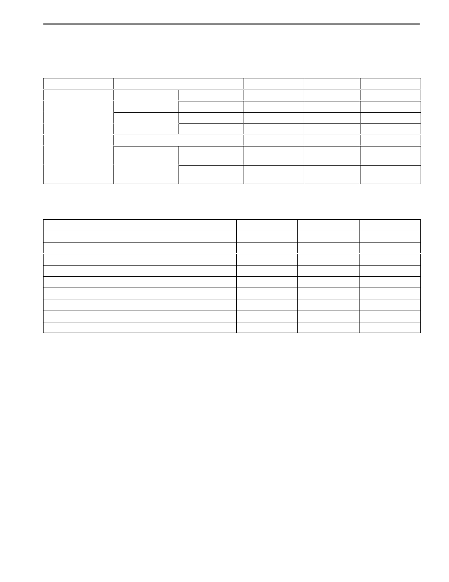
GENERAL SPECIFICATIONS
ÁÁÁÁÁÁÁÁ
ÁÁÁÁÁÁÁÁ
Application
ÁÁÁÁÁÁÁÁÁÁÁÁ
ÁÁÁÁÁÁÁÁÁÁÁÁ
Description
ÁÁÁÁÁÁ
ÁÁÁÁÁÁ
Unit
ÁÁÁÁÁÁ
ÁÁÁÁÁÁ
Standard
ÁÁÁÁÁÁÁ
ÁÁÁÁÁÁÁ
Limit
ÁÁÁÁÁÁÁÁ
ÁÁÁÁÁÁÁÁ
ÁÁÁÁÁÁÁ
ÁÁÁÁÁÁÁ
Inner
ÁÁÁÁÁÁ
ÁÁÁÁÁÁ
–
Tripot Joint
ÁÁÁÁÁÁÁ
ÁÁÁÁÁÁÁ
–
ÁÁÁÁÁÁÁÁ
ÁÁÁÁÁÁÁÁ
Type
ÁÁÁÁÁÁÁ
ÁÁÁÁÁÁÁ
Outer
ÁÁÁÁÁÁ
ÁÁÁÁÁÁ
–
Rzeppa Joint
ÁÁÁÁÁÁÁ
ÁÁÁÁÁÁÁ
–
ÁÁÁÁÁÁÁÁ
ÁÁÁÁÁÁÁÁ
ÁÁÁÁÁÁÁ
ÁÁÁÁÁÁÁ
Right
ÁÁÁÁÁÁ
ÁÁÁÁÁÁ
mm (in.)
553.5(21.79)
ÁÁÁÁÁÁÁ
ÁÁÁÁÁÁÁ
–
ÁÁÁÁÁÁÁÁ
ÁÁÁÁÁÁÁÁ
Length
ÁÁÁÁÁÁÁ
ÁÁÁÁÁÁÁ
Left
ÁÁÁÁÁÁ
ÁÁÁÁÁÁ
mm (in.)
386.5(15.22)
ÁÁÁÁÁÁÁ
ÁÁÁÁÁÁÁ
–
ÁÁÁÁÁÁÁÁ
ÁÁÁÁÁÁÁÁ
Drive Axle
Shaft Diameter
ÁÁÁÁÁÁ
ÁÁÁÁÁÁ
mm (in.)
22 (0.87)
ÁÁÁÁÁÁÁ
ÁÁÁÁÁÁÁ
–
ÁÁÁÁÁÁÁÁ
ÁÁÁÁÁÁÁÁ
ÁÁÁÁÁÁÁÁ
ÁÁÁÁÁÁÁ
ÁÁÁÁÁÁÁ
ÁÁÁÁÁÁÁ
Inner
ÁÁÁÁÁÁ
ÁÁÁÁÁÁ
ÁÁÁÁÁÁ
g (ounce)
90 – 100
(3.2 – 3.5)
ÁÁÁÁÁÁÁ
ÁÁÁÁÁÁÁ
ÁÁÁÁÁÁÁ
–
ÁÁÁÁÁÁÁÁ
ÁÁÁÁÁÁÁÁ
ÁÁÁÁÁÁÁÁ
Grease Capacity
ÁÁÁÁÁÁÁ
ÁÁÁÁÁÁÁ
ÁÁÁÁÁÁÁ
Outer
ÁÁÁÁÁÁ
ÁÁÁÁÁÁ
ÁÁÁÁÁÁ
g (ounce)
80 – 90
(2.8 – 3.2)
ÁÁÁÁÁÁÁ
ÁÁÁÁÁÁÁ
ÁÁÁÁÁÁÁ
–
FASTENER TIGHTENING SPECIFICATIONS
ÁÁÁÁÁÁÁÁÁÁÁÁÁÁÁÁÁÁ
ÁÁÁÁÁÁÁÁÁÁÁÁÁÁÁÁÁÁ
Application
ÁÁÁÁÁÁÁ
ÁÁÁÁÁÁÁ
N
S
m
ÁÁÁÁÁÁ
ÁÁÁÁÁÁ
Lb-Ft
ÁÁÁÁÁÁÁ
ÁÁÁÁÁÁÁ
Lb-In
ÁÁÁÁÁÁÁÁÁÁÁÁÁÁÁÁÁÁ
ÁÁÁÁÁÁÁÁÁÁÁÁÁÁÁÁÁÁ
Control Arm Ball Joint Bolt
ÁÁÁÁÁÁÁ
ÁÁÁÁÁÁÁ
50 – 70
ÁÁÁÁÁÁ
ÁÁÁÁÁÁ
36 – 52
ÁÁÁÁÁÁÁ
ÁÁÁÁÁÁÁ
–
ÁÁÁÁÁÁÁÁÁÁÁÁÁÁÁÁÁÁ
ÁÁÁÁÁÁÁÁÁÁÁÁÁÁÁÁÁÁ
Tie Rod End Joint castellated Nut
ÁÁÁÁÁÁÁ
ÁÁÁÁÁÁÁ
30 – 55
ÁÁÁÁÁÁ
ÁÁÁÁÁÁ
21 – 41
ÁÁÁÁÁÁÁ
ÁÁÁÁÁÁÁ
–
ÁÁÁÁÁÁÁÁÁÁÁÁÁÁÁÁÁÁ
ÁÁÁÁÁÁÁÁÁÁÁÁÁÁÁÁÁÁ
Stabilizer Bar Bolt
ÁÁÁÁÁÁÁ
ÁÁÁÁÁÁÁ
33 – 53
ÁÁÁÁÁÁ
ÁÁÁÁÁÁ
24 – 39
ÁÁÁÁÁÁÁ
ÁÁÁÁÁÁÁ
–
Stabilizer Bar Castellated Nut
40 – 50
30 – 36
–
ÁÁÁÁÁÁÁÁÁÁÁÁÁÁÁÁÁÁ
ÁÁÁÁÁÁÁÁÁÁÁÁÁÁÁÁÁÁ
Drive Axle Shaft Nut
ÁÁÁÁÁÁÁ
ÁÁÁÁÁÁÁ
210
ÁÁÁÁÁÁ
ÁÁÁÁÁÁ
155
ÁÁÁÁÁÁÁ
ÁÁÁÁÁÁÁ
–
ÁÁÁÁÁÁÁÁÁÁÁÁÁÁÁÁÁÁ
ÁÁÁÁÁÁÁÁÁÁÁÁÁÁÁÁÁÁ
Wheel Nut
ÁÁÁÁÁÁÁ
ÁÁÁÁÁÁÁ
90 – 110
ÁÁÁÁÁÁ
ÁÁÁÁÁÁ
66 – 81
ÁÁÁÁÁÁÁ
ÁÁÁÁÁÁÁ
–
Transaxle Under Cover Bolt
35 – 55
25 – 41
–
Oil Drain Plug
25 – 30
18 – 22
–
Oil Level Plug
36 – 54
26 – 40
–

MANUAL TRANSAXLE DRIVE AXLE 3B – 13
SPECIAL TOOLS AND EQUIPMENT
SPECIAL TOOLS TABLE
D104B101
KM–507–B
Tie Rod End
Joint Remover
D105B101
J–35566
Boot Clamp Pliers
SECTION 4A
HYDRAULIC BRAKES
CAUTION: Disconnect the negative battery cable before removing or installing any electrical unit or when a
tool or equipment could easily come in contact with exposed electrical terminals. Disconnecting this cable
will help prevent personal injury and damage to the vehicle. The ignition must also be in B unless otherwise
noted.
TABLE OF CONTENTS
Description and Operation
4A-2
. . . . . . . . . . . . . . . . . .
Warning Lamp Operation
4A-2
. . . . . . . . . . . . . . . . . . .
Component Locator
4A-3
. . . . . . . . . . . . . . . . . . . . . . . .
Brake System (Non-ABS)
4A-3
. . . . . . . . . . . . . . . . . .
Diagnostic Information and Procedures
4A-4
. . . . .
Brake System Testing
4A-4
. . . . . . . . . . . . . . . . . . . . . .
Brake Hose Inspection
4A-4
. . . . . . . . . . . . . . . . . . . . .
Warning Lamp Operation
4A-5
. . . . . . . . . . . . . . . . . . .
Brake System Fault
4A-5
. . . . . . . . . . . . . . . . . . . . . . . .
Manual Bleeding the Brakes
4A-6
. . . . . . . . . . . . . . . .
Pedal Travel Check
4A-6
. . . . . . . . . . . . . . . . . . . . . . . .
Brake Pedal Free Play Inspection
4A-7
. . . . . . . . . . .
Repair Instructions
4A-8
. . . . . . . . . . . . . . . . . . . . . . . . .
On-Vehicle Service
4A-8
. . . . . . . . . . . . . . . . . . . . . . . . . .
Brake Hose (Front)
4A-8
. . . . . . . . . . . . . . . . . . . . . . . .
Brake Hose (Rear)
4A-9
. . . . . . . . . . . . . . . . . . . . . . . .
Stoplamp Switch
4A-9
. . . . . . . . . . . . . . . . . . . . . . . . . .
Brake Pedal
4A-10
. . . . . . . . . . . . . . . . . . . . . . . . . . . . .
Specifications
4A-13
. . . . . . . . . . . . . . . . . . . . . . . . . . . .
General Specifications
4A-13
. . . . . . . . . . . . . . . . . . . .
Fastener Tightening Specifications
4A-13
. . . . . . . . . .
Schematic and Routing Diagrams
4A-14
. . . . . . . . . .
Brake Lamp Warning Circuit
4A-14
. . . . . . . . . . . . . . .
Stoplamp Switch Circuit
4A-14
. . . . . . . . . . . . . . . . . . .
Нет комментариевНе стесняйтесь поделиться с нами вашим ценным мнением.
Текст