Daewoo Musso. Manual — part 50
1B2-20 M161 ENGINE MECHANICAL
Operation When Full-Load at Partial Load
l
The throttle valve (6) is partially opened or fully opened.
The air flows very rapidly through the vent line(5)s
connection(D) and the intake air duct when full-load at partial
load.
Consequently, most of the low-by gases are supplied to the
combustion chamber through the timing gear case
cover(15), chain housing(17), oil separation chamber(3),
vent line(5), throttle valve(6), and intake manifold(8).

M161 ENGINE MECHANICAL 1B2-21
ALTERNATOR
Removal & Installation Procedure
1. Remove the drive belt.
2. Remove the alternator.
3. Unscrew the alternator carrier bolts (1,2,3) and remove the
carrier (4).
Installation Notice
Tightening Torque
22.5 - 27.5 Nm
Notice
Apply 3Nm of torque when mounting the bolt (1); apply 25 ±
2.5Nm of torque when mounting the bolts (2), and (3); and
then tighten the bolt (1) with 25 ± 2.5Nm of torque.
4. Installation should follow the removal procedure in the
reverse order.
1 Bolt (M8 X 40, 3 pieces) . . . . . 22.5-27.5 Nm
2 Bolt (M8 X 70, 2 pieces) . . . . . 22.5-27.5 Nm
3 Bolt (M8 X 85, 1 piece) . . . . ... 22.5-27.5 Nm
4 Alternator Bracket

1B2-22 M161 ENGINE MECHANICAL
POWER STEERING PUMP AND A/C BRACKET
Preceding Work : Removal of cooling fan and shroud
Removal of drive belt
1 Nut . . . . . . . . . . . . . 35.2-28.8 Nm
2 Washer
3 Belt Pulley
4 Bolt (M8 X 91, 2 pieces) . . . . . 22.5-27.5 Nm
5 Power Steering Pump
6 Bracket
7 Washer
8 Bolt (M8 X 20, 2 pieces) . . . . . 22.5-27.5 Nm
9 Washer
10 Bolt (M8 X 105,4 pieces) . . . . 22.5-27.5 Nm
11 A/C Compressor
12 Bolt (M8 X 50, 5 pieces, M8 X 80,
5 pieces) . . . . . . . . . . 22.5-27.5 Nm
13 A/C Bracket
14 Vent Hose
15 Bracket Gasket . . . . . . . . . .. Replace
M161 ENGINE MECHANICAL 1B2-23
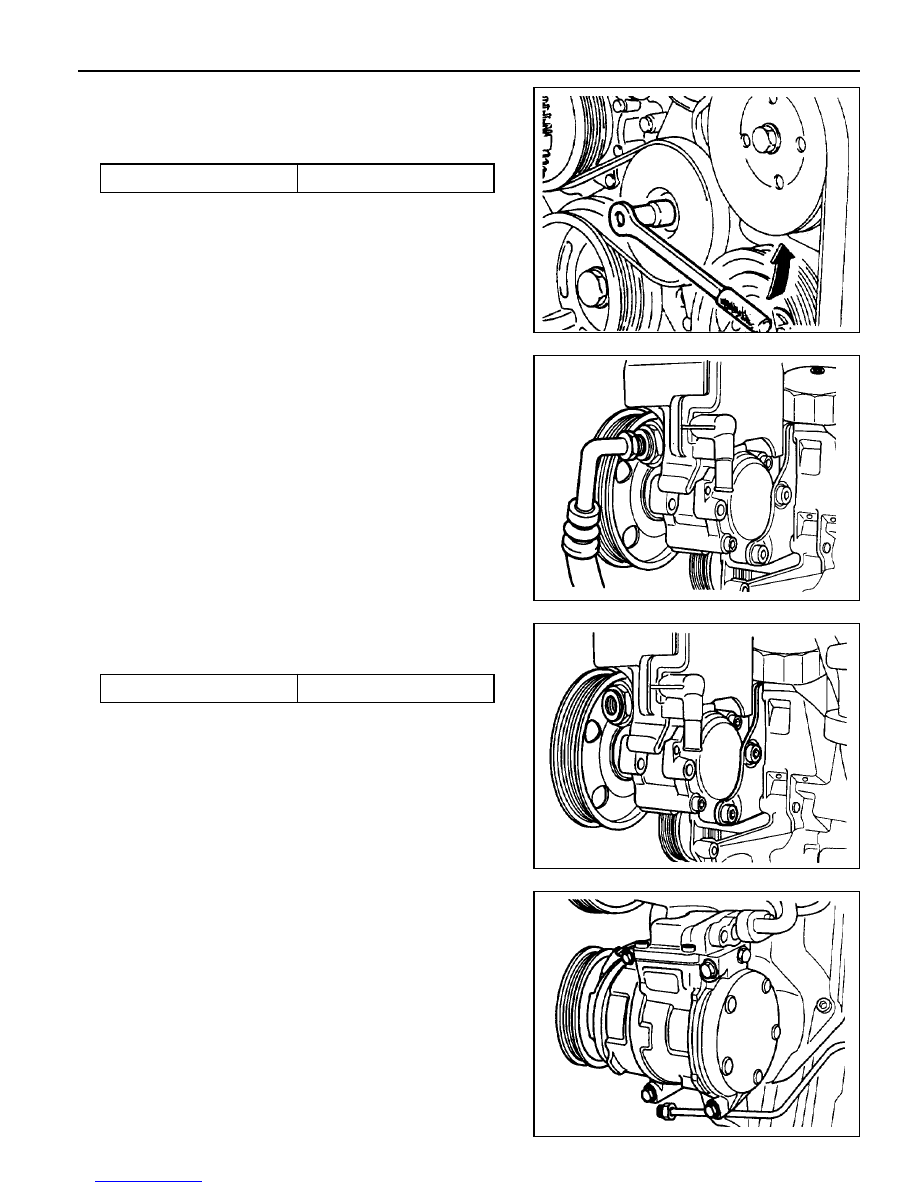
Removal & Installation Procedure
1. Remove the belt pulley after removal of poly v-belt.
Installation Notice
2. Disconnect the hydraulic pipe of the power steering pump
and drain the oil.
3. Unscrew the bolts (arrows) and remove the steering pump.
Installation Notice
Notice
Pull the tensioning pulley counterclockwise as shown in the
figure.
4. Remove the compressor after disconnecting the wiring
connector and refrigerant pipe of A/C compressor.
Notice
Discharge all the refrigerant before removing the pipes.
Tightening Torque
40.5 - 49.5 Nm
Tightening Torque
22.5 - 27.5 Nm
Нет комментариевНе стесняйтесь поделиться с нами вашим ценным мнением.
Текст