Daewoo Musso. Manual — part 49

1B2-16 M161 ENGINE MECHANICAL
30. Remove the transmission mounting bolts and separate
the transmission from the engine.
Installation Notice
Tightening Torque
65 Nm
31. Remove the bolts for engine mounting bracket.
Installation Notice
Tightening Torque
50 - 75 Nm
32. Hook the chain to the bracket of engine and by using a
hoist or crane, carefully separate the engine assembly
from the vehicle.
33. Installation should follow the removal procedure in the
reverse order.
M161 ENGINE MECHANICAL 1B2-17
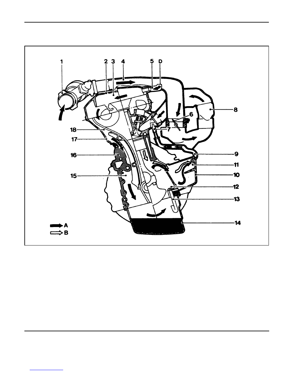
CRANKCASE VENTILATION SYSTEM
Operation at Idling and Mid-Load
1 HFM Sensor
2 Cylinder Head Cover
3 Oil Spearation Chamber (Full-Load or Over
Mid-Load)
4 Intake Air Duct (Cross Pipe)
5 Vent Line (Full-Load or Over Mid-Load)
6 Throttle Valve
7 Restrictor, Diameter 1.1mm (Mid-Load at Idling)
8 Intake Manifold
9 Vent Line (Mid-Load at Idling)
10 Air Conditioner Bracket
11 Oil Separation Chamber (Mid-Load at Idling)
12 Crank Chamber
13 Oil Return Pipe
14 Oil Pan
15 Timing Gear Case Cover
16 Crankcase
17 Chain Housing
A Fresh Air
C Blow-by Gas
D Vent Connection
1B2-18 M161 ENGINE MECHANICAL
Operation at Idling and Mid-Load
l
The throttle valve(6) is closed or very partially opened, and
the vacuum pressure in intake manifold is high.
The blow-by gas and the fresh air that is additionally supplied
through the vent connection(D) in the crankcase in partial
load gets supplied to the combustion chamber from the crank
chamber(12) through the oil separation chamber(11), air-
conditioner bracket(10), vent line(9), and restrictor(7)
mounted to the cylinder head.
The circulated engine oil returns to the oil pan through the
oil return pipe(13) at the bottom of oil separation
chamber(11).
The fresh air gets supplied to the crank chamber(12) through
the HFM sensor(1), intake air duct(4), vent line(5), oil
separation chamber(3), chain housing(17), and the timing
gear case cover(15).
The additional supply of the fresh air is needed to prevent
from forming the residues of the engine oil.

M161 ENGINE MECHANICAL 1B2-19
Operation When Full-Load at Partial Load
1 HFM Sensor
2 Cylinder Head Cover
3 Oil Spearation Chamber (Full-Load or Over
Mid-Load)
4 Intake Air Duct (Cross Pipe)
5 Vent Line (Full-Load or Over Mid-Load)
6 Throttle Valve
7 Restrictor, Diameter 1.1mm (Mid-Load at Idling)
8 Intake Manifold
9 Vent Line (Mid-Load at Idling)
10 Air Conditioner Bracket
11 Oil Separation Chamber (Mid-Load at Idling)
12 Crank Chamber
13 Oil Return Pipe
14 Oil Pan
15 Timing Gear Case Cover
16 Crankcase
17 Chain Housing
A Fresh Air
C Blow-by Gas
D Vent Connection
Нет комментариевНе стесняйтесь поделиться с нами вашим ценным мнением.
Текст