Daewoo Musso. Manual — part 21
1B1-20 M162 ENGINE MECHANICAL
Removal & Installation Procedure
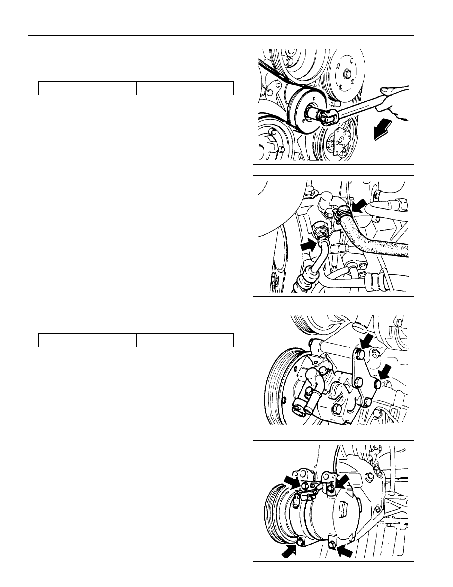
1. Remove the belt pulley.
Installation Notice
2. Disconnect the hydraulic pipe of the power steering pump
and drain the oil.
3. Unscrew the bolts (arrows) and remove the steering pump.
Installation Notice
Notice
Pull the tensioning pulley clockwise as shown in the figure.
4. Remove the compressor after disconnecting the wiring
connector and refrigerant pipe of A/C compressor.
Notice
Discharge all the refrigerant before removing the pipes.
Tightening Torque
40.5 - 49.5 Nm
Tightening Torque
22.5 - 27.5 Nm

M162 ENGINE MECHANICAL 1B1-21
5. Disconnect the vent hose from the A/C bracket.
6. Unscrew all the mounting bolts (arrows) and remove the
A/C bracket and the gasket.
Installation Notice
7. Clean the sealing surface.
8. Replace the gasket with new one.
9. Installation should follow the removal procedure in the
reverse order.
10. Check the oil leakage by operating the engine after
installation.
Tightening Torque
22.5 - 27.5 Nm
1B1-22 M162 ENGINE MECHANICAL
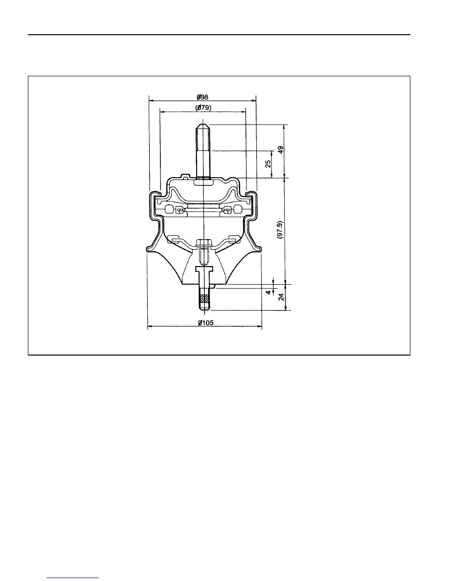
HYDRAULIC ENGINE MOUNTING INSULATOR
Service Data

M162 ENGINE MECHANICAL 1B1-23
Sectional View
1 Rubber Body
2 Brackek
3 Core
4 Lower Bolt
5 Rubber Plunger
6 Plunger Plate
7 Rubber
8 Plate
9 Lower Orifice
10 Upper Orifice
11 Diaphram
12 Cover Plate
13 Upper Bolt
14 Flange Bolt
15 Rivet
16 Fluid
Нет комментариевНе стесняйтесь поделиться с нами вашим ценным мнением.
Текст