Chery Tiggo 5 (T21). Service manual — part 136
09–
5
09
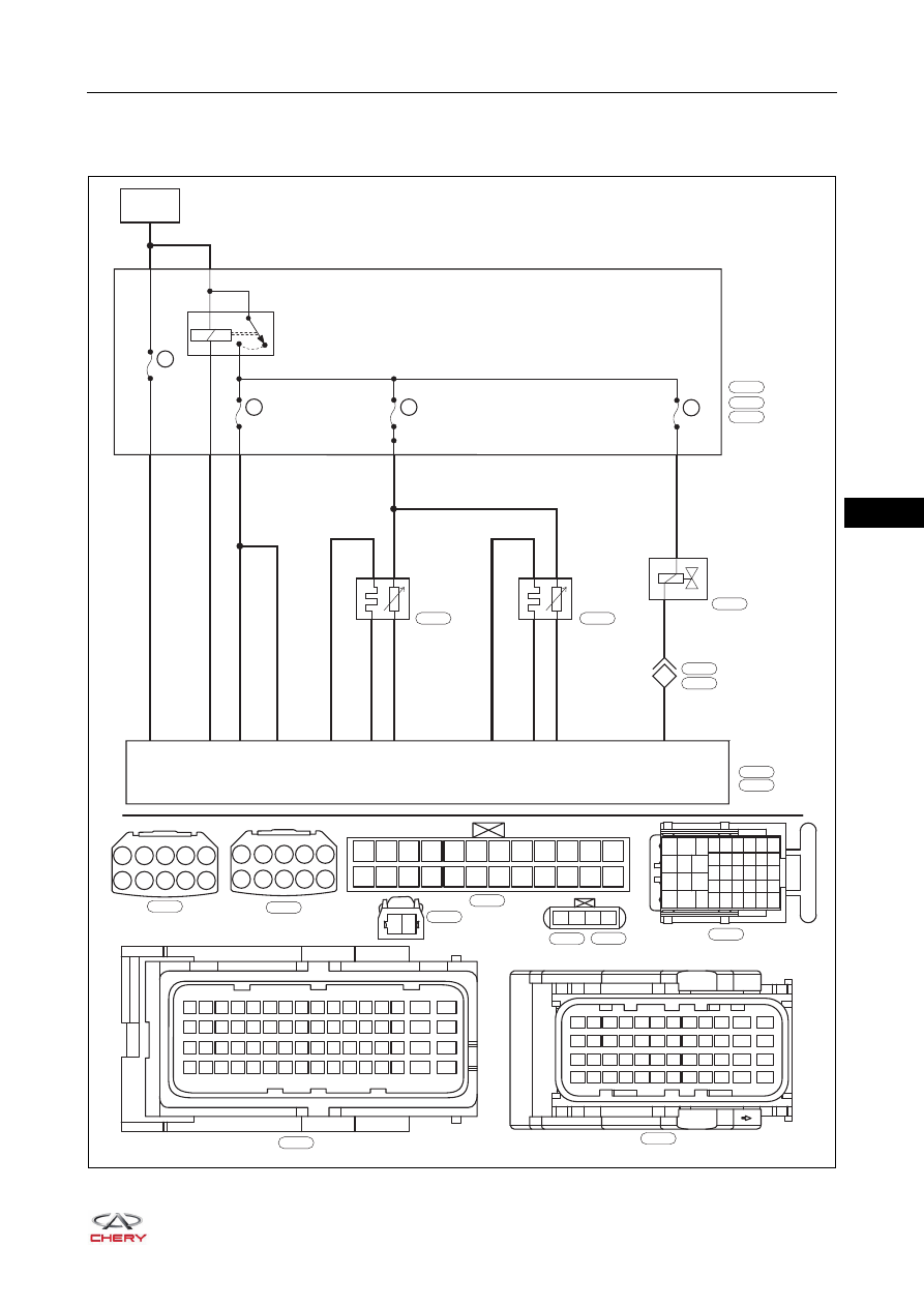
Circuit Diagram
Emission Control System
ET21090010
A1
A2
A3
A4
A5
A6
A7
A8 A9 A10
F12
F24
F11
F23
F10
F22
F9
F21
F8
F20
F7
F19
F6
F18
F5
F17
F4
F16
F3
F15
F2
F14
F1
F13
1
2
3
4
Gr
E-076
W
E-069
B
E-043
B
E-084
B
E-033
49 50 51
63
64
15
16
31
32
47
48
33 34 35
17 18 19
1
2
3
52 53 54 55 56 57 58 59 60 61 62
36 37 38 39 40 41 42 43 44 45 46
20 21 22 23 24 25 26 27 28 29 30
4
5
6
7
8
9 10 11 12 13 14
BATTERY
ECM
MAIN
RELAY
ECM
10A
EF19
10A
EF40
10A
EF39
A2
F14
2-20
RL
2-5
Br
A6
A7
2-15
2-16
2-21
RR
R
R
R
R
WG
YL
GW
RL
YL
GL
86
30
85
87
REAR
OXYGEN
SENSOR
2-48
1-40
2-43
1-9
3
1-16
1
4
2
3
4
2
1
FRONT
OXYGEN
SENSOR
ENGINE
COMPARTMENT
FUSE AND
RELAY BOX
E-043
E-084
E-076
E-069
E-023
E-033
E-035
RL
C9
L
L
1-30
2
1
11
CANISTER
SOLENOID
VALVE
E-007
E-038
E-024
10A
EF27
1
2
3
4
5
6
7
8
9
10
11
12
13
14
15
16
17
18
19
20
21
22
23
24
25
26
31
35
39
40
41
42
32
33
36
37
38 34
27
28
29
30
C1
C2
C3 C4
C5
C6
C7
C8 C9 C10
L
E-023
B
E-007
1
2
B
E-024
37 38 39 40 41 42 43 44 45 46
47
48
25 26 27 28 29 30 31 32 33 34
35
36
13 14 15 16 17 18 19 20 21 22
23
24
1
2
3
4
5
6
7
8
9 10
11
12
B
E-035
09–
6
09
DIAGNOSIS & TESTING
Leakage Inspection
Visually check that hoses, connections and gaskets have no cracks, leaks or damage.
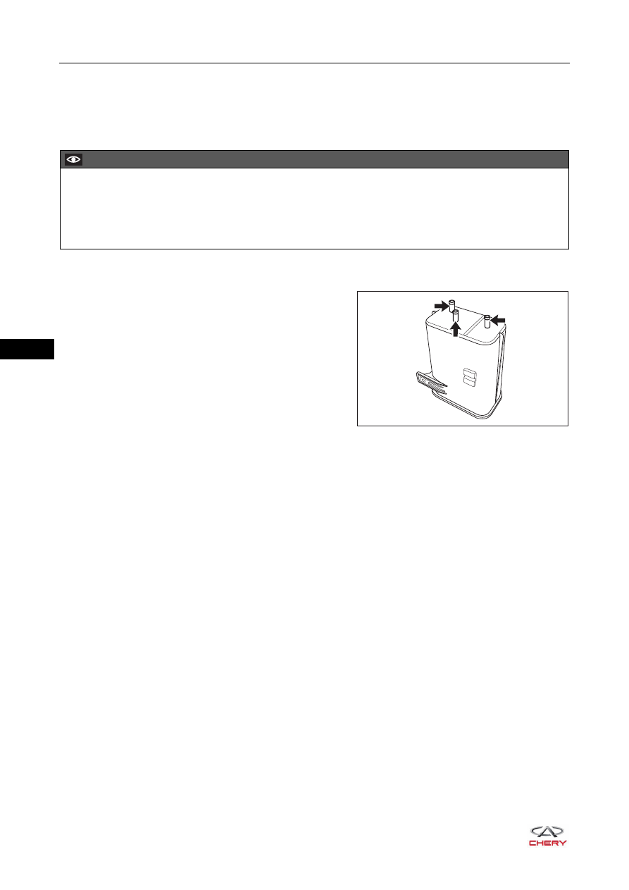
Activated Charcoal Canister Inspection
1. Close port C and blow compressed air into port A, check
that air flows from port B. If result is not as specified,
replace canister.
2. Close port C and blow compressed air into port B, check
that air flows from port A. If result is not as specified,
replace canister.
Fuel Tank Cap Assembly Inspection
1. Visually check that fuel tank cap assembly is not
deformed or damaged.
2. If result is not as specified, replace fuel tank cap
assembly.
CAUTION
Removal of engine oil dipstick, filler cap, PCV hose and other components or other problems in them
may cause engine to run improperly.
Air suction caused by disconnections, looseness or cracks in intake system pipes related with throttle
assembly will result in engine failure or abnormal operation. Replace parts as necessary.
C
A
B
RT21090020
09–
7
09
ON-VEHICLE SERVICE
Activated Charcoal Canister Solenoid Valve and Bracket
Removal
1. Turn off all the electrical equipment and ignition switch.
2. Disconnect the negative battery cable.
3. Remove the engine trim cover assembly (
).
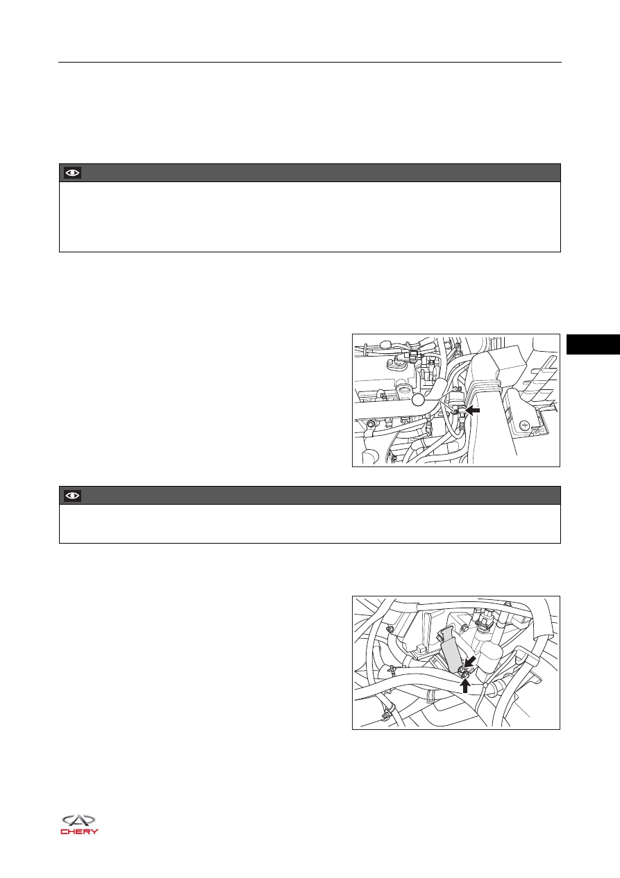
4. Remove the activated charcoal canister solenoid valve.
a. Disconnect the canister solenoid valve connector
(arrow).
b. Disengage the clamps (1) and disconnect both ends
of canister solenoid valve from the hose.
c. Remove the canister solenoid valve from the bracket.
5. Remove the activated charcoal canister solenoid valve bracket.
a. Remove 2 fixing bolts (arrow) from the activated
charcoal canister solenoid valve bracket, and remove
the activated charcoal canister solenoid valve bracket.
(Tightening torque: 7 ± 1 N·m)
CAUTION
Be sure to wear necessary safety equipment when repairing to prevent accidents.
Try to prevent body paint surface from being scratched during removal and installation.
Before removal, mark fuel vapor pipe III assembly and outlet hose to avoid confusion.
1
RT21090030
CAUTION
Positioning distance from hose end to clamp is 3 - 5 mm.
RT21090040
09–
8
09
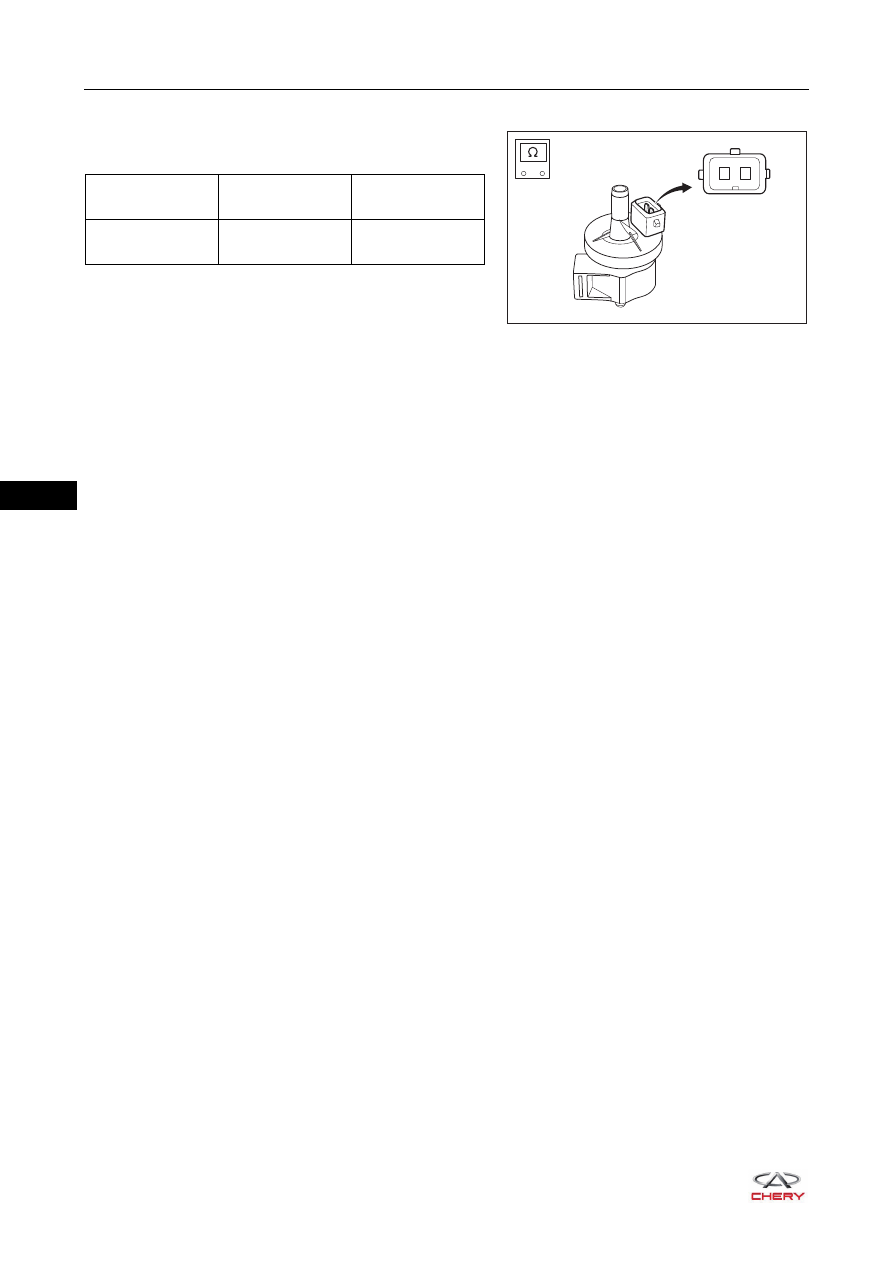
Inspection
Measure resistance between 2 pins of canister solenoid with
a digital multimeter.
Installation
Installation is in the reverse order of removal.
-
+
2
1
RT21090050
Multimeter
Connection
Measurement
Temperature
Specification (Ω)
Terminal 1 -
Terminal 2
20°C
26 ± 4
Нет комментариевНе стесняйтесь поделиться с нами вашим ценным мнением.
Текст