Chery Tiggo 5 (T21). Service manual — part 110
07–
26
07
Idler Pulley Assembly
Removal
1. Turn off all the electrical equipment and ignition switch.
2. Disconnect the negative battery cable.
3. Remove the engine trim cover assembly (
).
4. Remove the engine lower right protector assembly (
).
5. Remove the accessory drive belt (
).
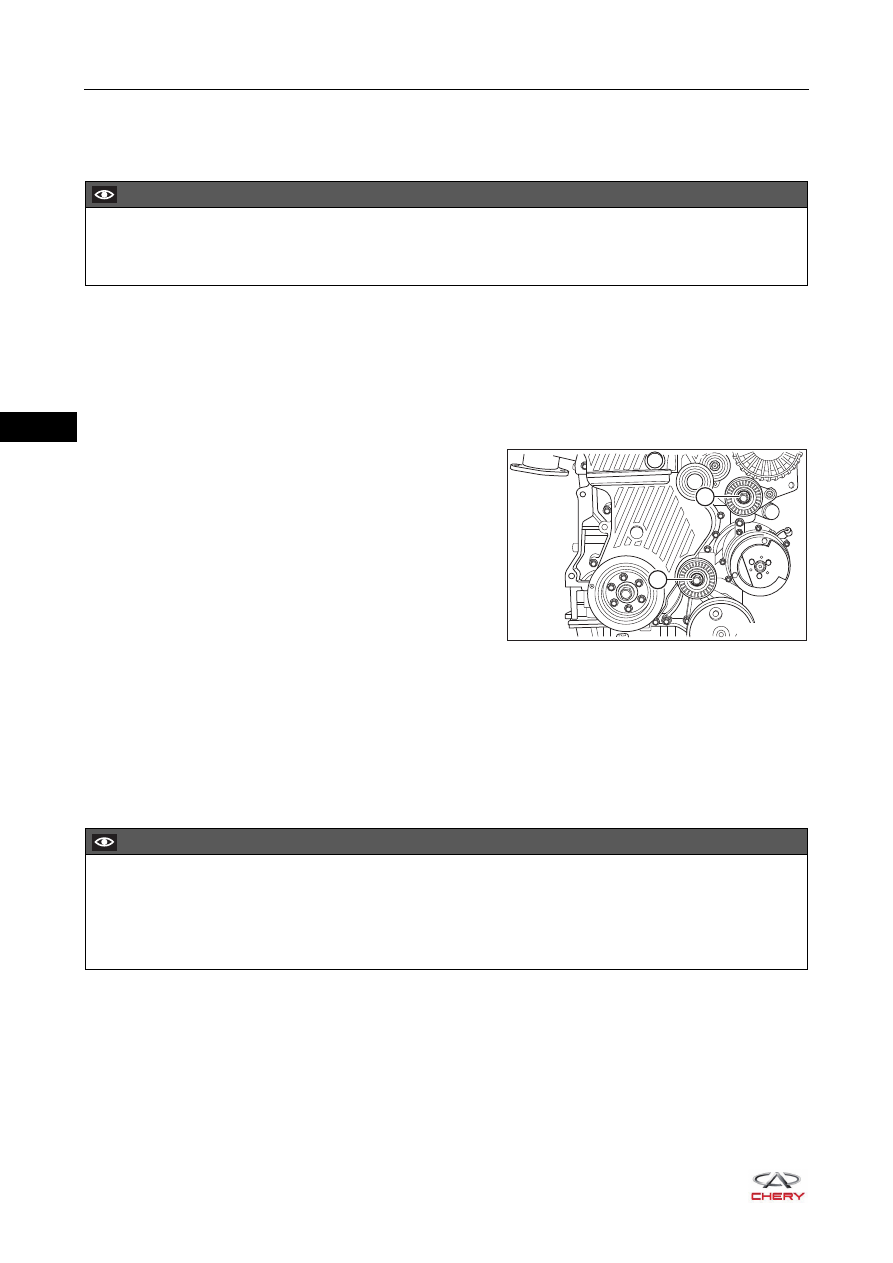
6. Remove the idler pulley assembly.
a. Remove the fixing bolt (1) from upper idler pulley
assembly, and remove the upper idler pulley
assembly.
(Tightening torque: 40 + 5 N·m)
b. Remove the fixing bolt (2) from lower idler pulley
assembly, and remove the lower idler pulley
assembly.
(Tightening torque: 40 + 5 N·m)
Inspection
1. Rotate idler pulley assembly by hands and check if the rotation is smooth and if abnormal noise occurs.
2. Wiggle idler pulley assembly in the axial and radial direction to check the bearing for looseness.
3. Check if there is damage on idler pulley assembly operating surface.
Installation
Installation is in the reverse order of removal.
CAUTION
Be sure to wear necessary safety equipment to prevent accidents when repairing.
Try to prevent body paint surface from being scratched during removal and installation.
RT21070050
1
2
CAUTION
After installation, turn crankshaft with a wrench to run accessory drive belt several circles, and check if
crankshaft turns smoothly and belt runs well. If it does not turn smoothly, reinstall the accessory drive
belt.
Make sure to install accessory drive belt in place, and not interfere with other components.
07–
27
07
Belt Tensioner Assembly
Removal
1. Turn off all the electrical equipment and ignition switch.
2. Disconnect the negative battery cable.
3. Remove the engine trim cover assembly (
).
4. Remove the accessory drive belt (
).
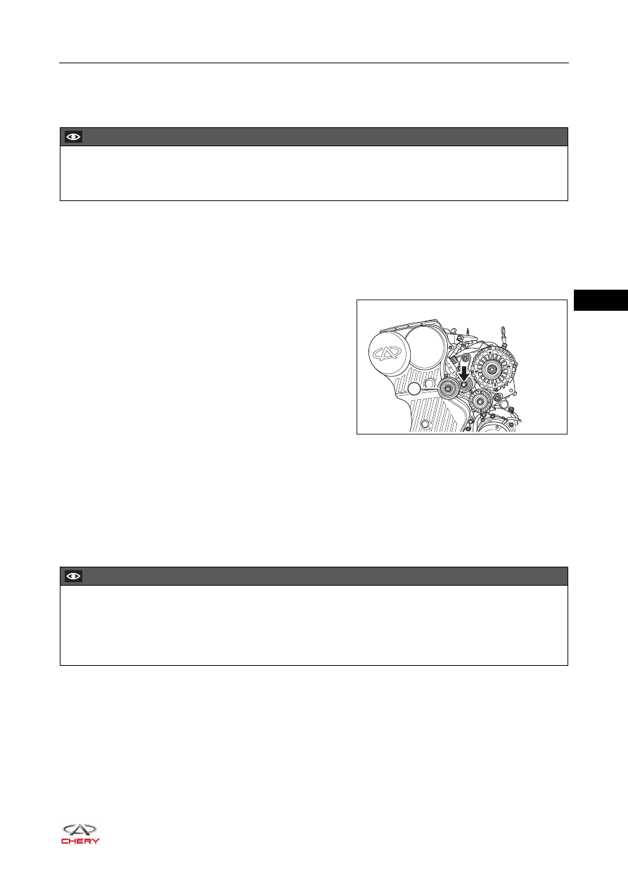
5. Remove the belt tensioner assembly.
a. Remove the fixing bolt from belt tensioner assembly,
and remove the belt tensioner assembly (1).
(Tightening torque: 40 + 5 N·m)
Inspection
1. Rotate tensioner assembly by hands and check if the rotation is smooth and if abnormal noise occurs.
2. Wiggle tensioner assembly in the axial and radial direction to check the bearing for looseness.
3. Check if there is damage on tensioner assembly operating surface.
Installation
Installation is in the reverse order of removal.
CAUTION
Be sure to wear necessary safety equipment to prevent accidents when repairing.
Try to prevent body paint surface from being scratched during removal and installation.
1
RT21070060
CAUTION
After installation, turn crankshaft with a wrench to run accessory drive belt several circles, and check if
crankshaft turns smoothly and belt runs well. If it does not turn smoothly, reinstall the accessory drive
belt.
Make sure to install accessory drive belt in place, and not interfere with other components.
07–
28
07
Engine Timing Belt
Description
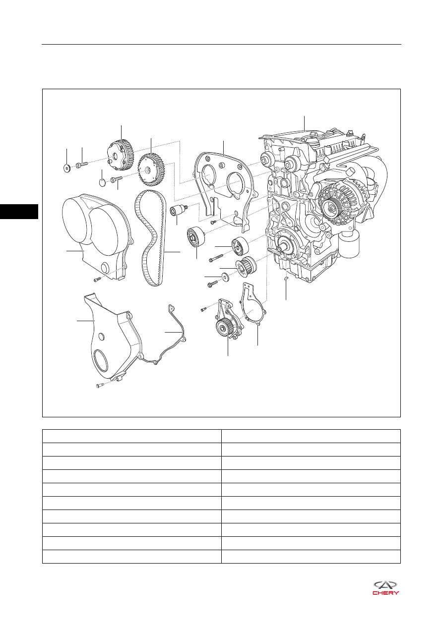
1 - Engine Assembly
2 - Timing Belt Rear Cover
3 - Intake Camshaft Phaser Assembly
4 - Exhaust Camshaft Phaser Assembly
5 - Exhaust Camshaft Phaser Assembly Fixing Bolt
6 - Exhaust Phaser Cover
7 - Intake Phaser Cover
8 - Intake Camshaft Phaser Assembly Fixing Bolt
9 - Contacting Idler Pulley
10 - Timing Belt Front Cover Upper Body
11 - Timing Belt
12 - Timing Belt Idler Pulley
13 - Timing Belt Tensioner
14 - Crankshaft Timing Pulley
15 - Camshaft Timing Pulley Fixing Bolt Washer
16 - Timing Belt Front Cover Lower Body
17 - Timing Belt Front Cover Lower Body Gasket
18 - Water Pump Assembly
19 - Water Pump Assembly Gasket
20 - Semi-circle Key
RT21070070
3159B
5/
8
1
3
×6
×5
×5
×6
12
18
19
20
9
8
6
7
5
4
2
3
1
11
13
15
17
16
14
10
07–
29
07
Removal
1. Turn off all the electrical equipment and ignition switch.
2. Disconnect the negative battery cable.
3. Remove the engine trim cover assembly (
).
4. Remove the engine lower right protector assembly (
).
5. Remove the accessory drive belt (
).
6. Remove the belt tensioner assembly (
).
7. Use an engine equalizer to hang the engine right lifting eye.
8. Remove the engine right mounting (
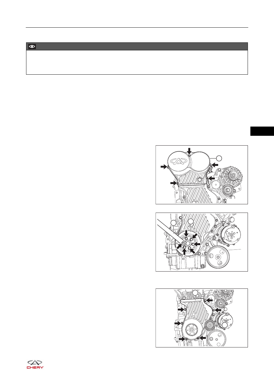
9. Remove the timing belt front cover.
a. Loosen and remove 5 fixing bolts (arrow) from timing
belt front cover upper body, and remove the timing
belt front cover upper body (1).
(Tightening torque: 7 N·m)
b. Loosen and remove 6 fixing bolts (arrow) from
crankshaft pulley, and remove the crankshaft pulley
(1).
(Tightening torque: 1st step: tighten to 25 ± 5 N·m;
2nd step: retighten by 30° ± 5°)
HINT:
Shift the transmission into 5th gear (for MT model) or
D position (for CVT model) when loosening the
crankshaft timing gear fixing bolt to engage the
crankshaft and propeller shaft. Another technician
depresses the brake pedal, which can lock the
crankshaft by mechanical gear train.
c. Loosen and remove the fixing bolt from accessory
drive belt lower idler pulley assembly, and remove the
accessory drive belt lower idler pulley assembly (1).
(Tightening torque: 40 + 5 N·m)
d. Loosen and remove 6 fixing bolts (arrow) from timing
belt front cover lower body, and remove the timing belt
front cover lower body (2).
(Tightening torque: 7 N·m)
CAUTION
Be sure to wear necessary safety equipment to prevent accidents when repairing.
Try to prevent body paint surface from being scratched during removal and installation.
RT21070080
1
RT21070090
2
1
RT21070100
2
1
Нет комментариевНе стесняйтесь поделиться с нами вашим ценным мнением.
Текст