Lexus SC300 / Lexus SC400. Service manual — part 112
REMOVAL OF SLIDING ROOF HOUSING
(See pages
to 87)
1.
REMOVE FOLLOWING PARTS:
(a) Interior light (See step 2 on page
(b) Front pillar garnish (See step 2 on page
(c) Rear seat cushion, rear seat back
(See steps 1 to 2 on page
(d) Roof side inner garnish (See step 8 on page
)
(e) Center visor (See step 4 on page
(f) Shoulder belt anchor (See step 7 on page
(g) Sun visor (See step 3 on page
(h) Sliding roof garnishes (See step 4 on page
(i)
Roof headlining (See step 2 on page
)
(j)
Sliding roof glass (See step 5 on page
)
(k) Quarter trim (See step 7 on page
2.
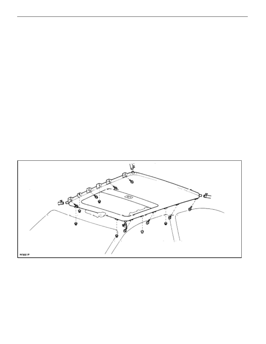
REMOVE SLIDING ROOF HOUSING
(a) Disconnect the four drain hoses from the housing.
(b) Disconnect the connectors.
(c) Remove eight bolts.
(d) While supporting the housing, remove six nuts and the
housing.
3.
REMOVE FOLLOWING PARTS:
(a) Drive gear assembly (See step 6 on page
(b) Sliding roof control relay
(c) Wind deflector (See step 7 on page
(d) Cable guide casing (See step 8 on page
)
(e) Roof drip channel (See step 9 on page
)
(f) Sunshade trim (See step 10 on page
(g) Drive rail (See step 11 on page
–
BODY
Moon Roof (Sliding Roof)
BO–89
INSTALLATION OF SLIDING ROOF
HOUSING
(See pages
to 87)
1. INSTALL SLIDING ROOF PARTS BY FOLLOWING
REMOVAL SEQUENCE IN REVERSE
HINT:
When installing the sliding roof housing weather-
strip, make sure that there is no clearance in either lip of the
weatherstrip.
2.
TORQUE FOLLOWING BOLTS:
(a) Rear seat back
Torque: 18
N
⋅
m (185 kgf
⋅
cm, 13 ft
⋅
lbf)
(b) Rear seat inner belt
Torque: 43
N
⋅
m (440 kgf
⋅
cm, 32 ft
⋅
lbf)
(c) Front seat belt shoulder anchor bolt
Torque: 43
N
⋅
m (440 kgf
⋅
cm, 32 ft
⋅
lbf)
BO–90
–
BODY
Moon Roof (Sliding Roof)
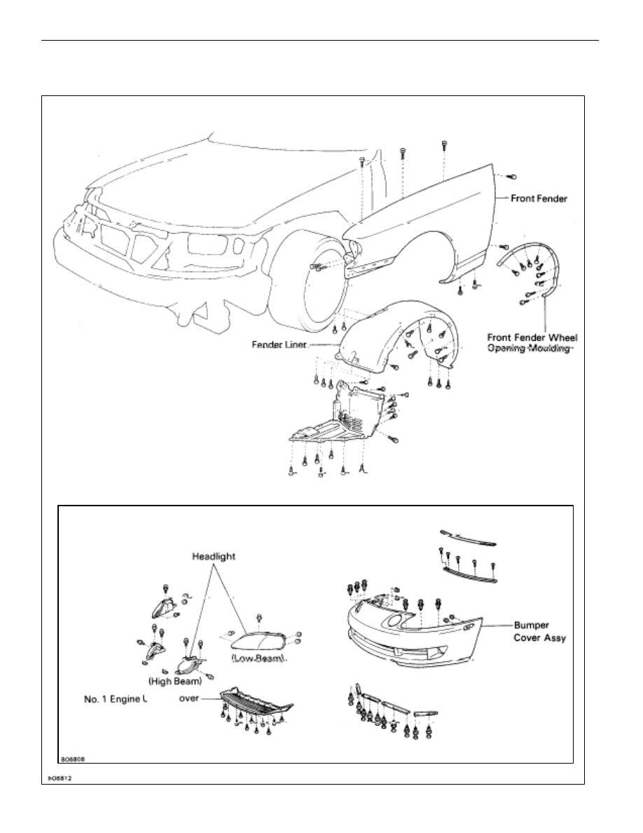
FRONT FENDER
COMPONENTS
Front Bumper
–
BODY
Front Fender
BO–91
REMOVAL OF FRONT FENDER
(See page
1.
REMOVE FRONT BUMPER
(See page
2. REMOVE
FRONT FENDER WHEEL OPENING MOULDING
(See page
)
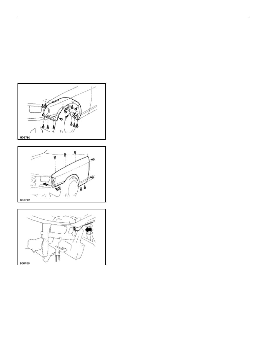
3.
REMOVE FENDER LINER
(a) Remove eight screws.
(b) Remove the liner with four clips.
4.
REMOVE FRONT FENDER
Remove eleven bolts and the fender.
CAUTION: Do not damage or shock the front airbag
sensor at all.
INSTALLATION OF FRONT FENDER
(See page
1.
INSTALL FRONT FENDER
Install eleven bolts and the fender.
BO–92
–
BODY
Front Fender
Нет комментариевНе стесняйтесь поделиться с нами вашим ценным мнением.
Текст