Nissan Murano Z51. Instruction — part 307
C1116 STOP LAMP SWITCH
BRC-51
< DTC/CIRCUIT DIAGNOSIS >
[VDC/TCS/ABS]
C
D
E
G
H
I
J
K
L
M
A
B
BRC
N
O
P
Is the inspection result normal?
YES
>> Replace ABS actuator and electric unit (control unit). Refer to
.
NO
>> Repair or replace error-detected parts.
Component Inspection
INFOID:0000000005517307
1.
CHECK STOP LAMP SWITCH
1.
Turn the ignition switch OFF.
2.
Disconnect stop lamp switch connector.
3.
Check the continuity between stop lamp switch connector terminals.
Is the inspection result normal?
YES
>> INSPECTION END
NO
>> Replace stop lamp switch. Refer to
.
Special Repair Requirement
INFOID:0000000005532215
1.
ADJUSTMENT OF STEERING ANGLE SENSOR NEUTRAL POSITION AND CALIBRATION OF DECEL G
SENSOR
After removing/replacing an ABS actuator and electric unit (control unit), be sure to perform the following pro-
cedure.
• Adjustment of steering angle sensor neutral position: Refer to
BRC-9, "ADJUSTMENT OF STEERING
ANGLE SENSOR NEUTRAL POSITION : Description"
.
• Calibration of decel G sensor: Refer to
BRC-10, "CALIBRATION OF DECEL G SENSOR : Description"
.
>> END
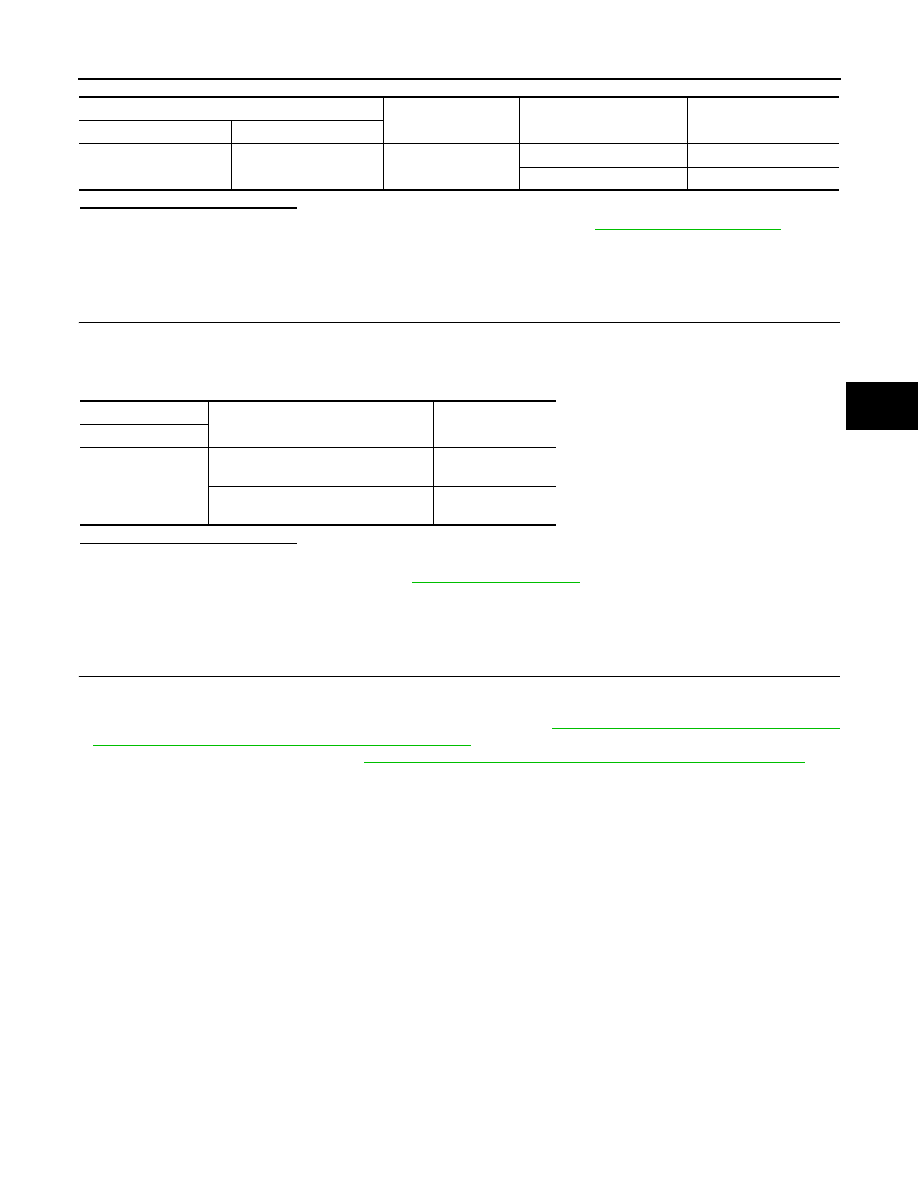
ABS actuator and electric unit (control unit)
—
Condition
Voltage
Connector
Terminal
E36
16
Ground
Brake pedal is depressed
Battery voltage
Brake pedal is released
Approx. 0 V
Stop lamp switch
Condition
Continuity
Terminal
1
−
2
Release stop lamp switch
(When brake pedal is depressed.)
Existed
Push stop lamp switch
(When brake pedal is released.)
Not existed
BRC-52
< DTC/CIRCUIT DIAGNOSIS >
[VDC/TCS/ABS]
C1120, C1122, C1124, C1126 IN ABS SOL
C1120, C1122, C1124, C1126 IN ABS SOL
Description
INFOID:0000000005517309
The solenoid valve increases, holds or decreases the fluid pressure of each brake caliper according to the sig-
nals transmitted by the ABS actuator and electric unit (control unit).
DTC Logic
INFOID:0000000005517310
DTC DETECTION LOGIC
DTC CONFIRMATION PROCEDURE
1.
DTC REPRODUCTION PROCEDURE
1.
Turn the ignition switch ON.
2.
Perform self-diagnosis for “ABS” with CONSULT-III.
Is DTC “C1120”, “C1122”, “C1124” or “C1126” detected?
YES
>> Proceed to diagnosis procedure. Refer to
.
NO
>> INSPECTION END
Diagnosis Procedure
INFOID:0000000005517311
1.
CHECK CONNECTOR
1.
Turn the ignition switch OFF.
2.
Disconnect ABS actuator and electric unit (control unit) connector.
3.
Check terminal for deformation, disconnection, looseness, etc.
Is the inspection result normal?
YES
>> GO TO 2.
NO
>> Replace or repair error-detected parts.
2.
CHECK SOLENOID, VDC SWITCH-OVER VALVE AND ACTUATOR RELAY POWER SUPPLY CIRCUIT
Check the voltage between ABS actuator and electric unit (control unit) harness connector and ground.
Is the inspection result normal?
YES
>> GO TO 3.
NO
>> Repair or replace error-detected parts.
3.
CHECK SOLENOID, VDC SWITCH-OVER VALVE AND ACTUATOR RELAY GROUND CIRCUIT
Check the continuity between ABS actuator and electric unit (control unit) harness connector and ground.
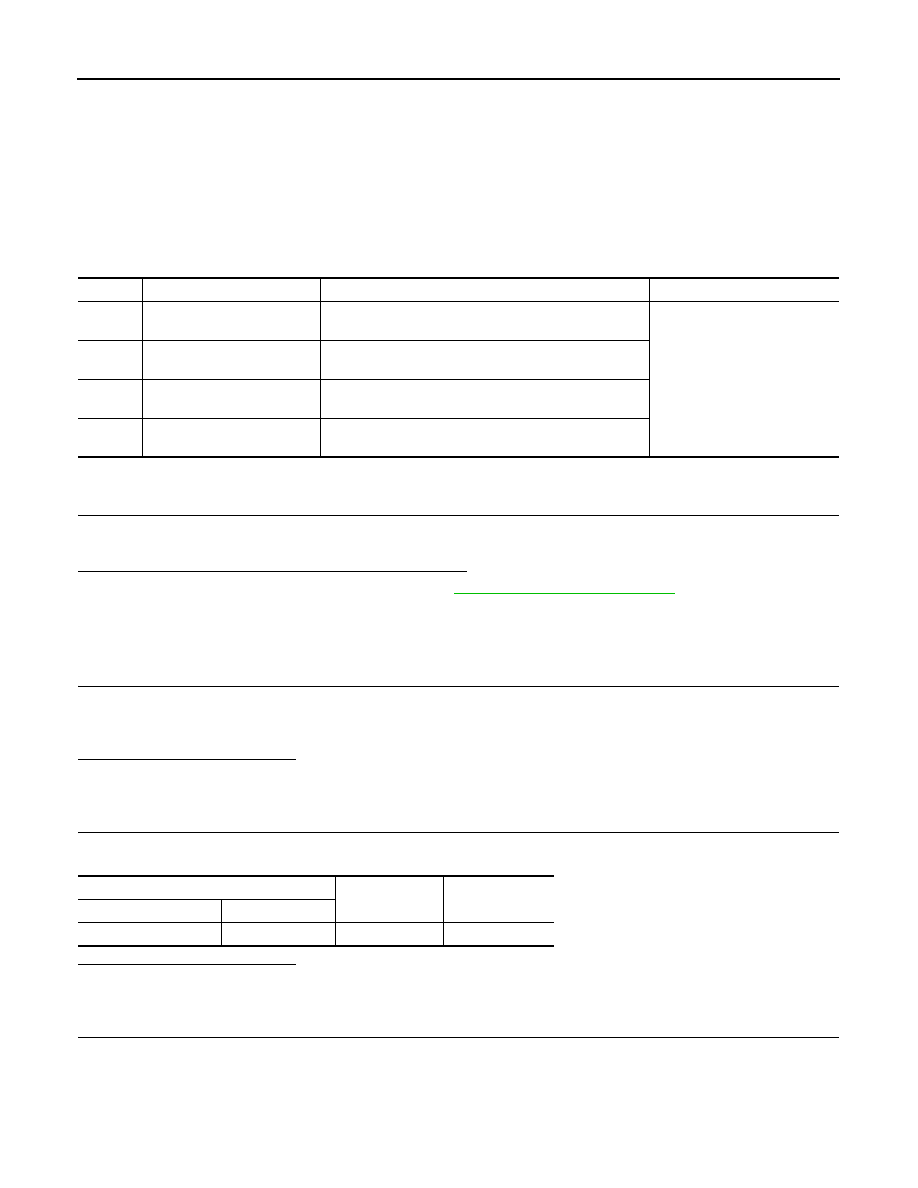
DTC
Display item
Malfunction detected condition
Possible cause
C1120
FR LH IN ABS SOL
When the control unit detects a malfunction in the front
LH inlet solenoid circuit.
• Harness or connector
• ABS actuator and electric unit
(control unit)
C1122
FR RH IN ABS SOL
When the control unit detects a malfunction in the front
RH inlet solenoid circuit.
C1124
RR LH IN ABS SOL
When the control unit detects a malfunction in the rear LH
inlet solenoid circuit.
C1126
RR RH IN ABS SOL
When the control unit detects a malfunction in the rear
RH inlet solenoid circuit.
ABS actuator and electric unit (control unit)
—
Voltage
Connector
Terminal
E36
1
Ground
Battery voltage
C1120, C1122, C1124, C1126 IN ABS SOL
BRC-53
< DTC/CIRCUIT DIAGNOSIS >
[VDC/TCS/ABS]
C
D
E
G
H
I
J
K
L
M
A
B
BRC
N
O
P
Is the inspection result normal?
YES
>> Replace ABS actuator and electric unit (control unit). Refer to
.
NO
>> Repair or replace error-detected parts.
Component Inspection
INFOID:0000000005517312
1.
CHECK ACTIVE TEST
1.
Select “ABS”, “ACTIVE TEST” and each test menu item in order with CONSULT-III.
2.
Select “Up”, “Keep”, and “Down”, and check that the system operates as shown in the table below.
*: On for 1 to 2 seconds after the select, and then Off.
NOTE:
A brief moment of On/Off condition occurs every 20 seconds after ignition switch turned ON. This is not malfunction because it is a
operation for checking.
Is the inspection result normal?
YES
>> INSPECTION END
NO
>> Proceed to diagnosis procedure. Refer to
.
Special Repair Requirement
INFOID:0000000005532216
1.
ADJUSTMENT OF STEERING ANGLE SENSOR NEUTRAL POSITION AND CALIBRATION OF DECEL G
SENSOR
After removing/replacing an ABS actuator and electric unit (control unit), be sure to perform the following pro-
cedure.
• Adjustment of steering angle sensor neutral position: Refer to
BRC-9, "ADJUSTMENT OF STEERING
ANGLE SENSOR NEUTRAL POSITION : Description"
.
• Calibration of decel G sensor: Refer to
BRC-10, "CALIBRATION OF DECEL G SENSOR : Description"
.
>> END
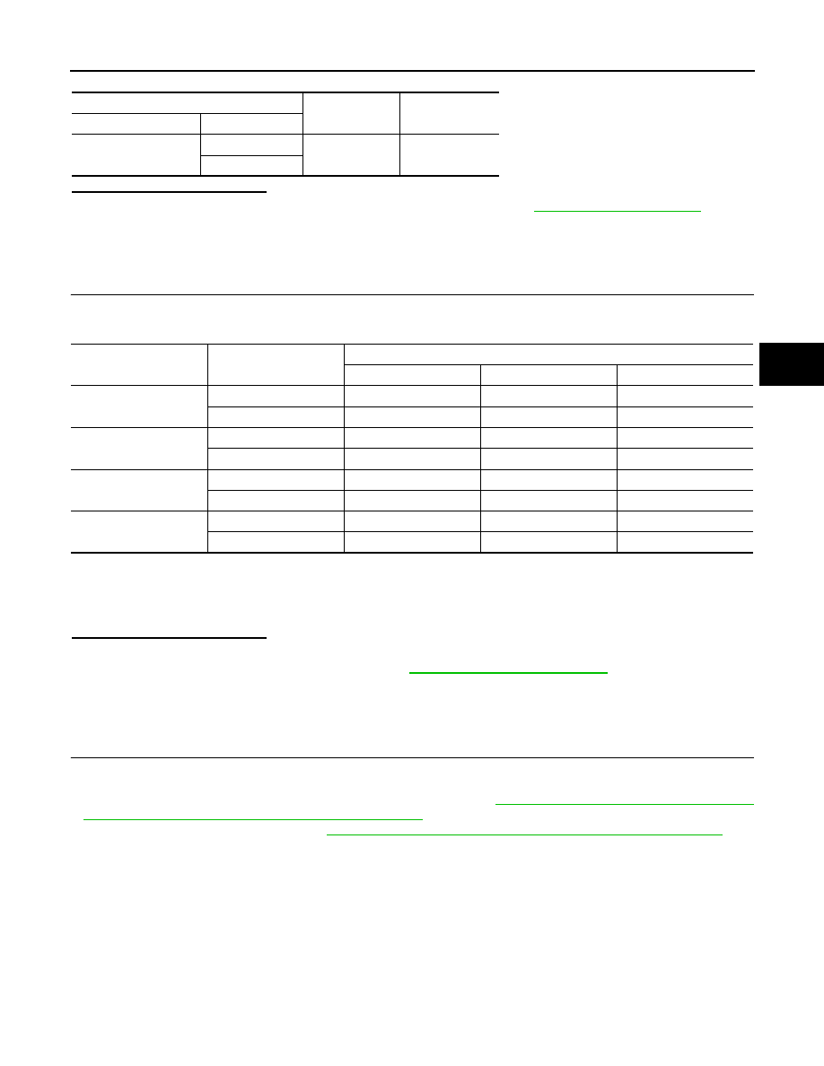
ABS actuator and electric unit (control unit)
—
Continuity
Connector
Terminal
E36
13
Ground
Existed
26
Test item
Display item
Display
Up
Keep
Down
FR RH SOL
FR RH IN SOL
Off
On
On
FR RH OUT SOL
Off
Off
On*
FR LH SOL
FR LH IN SOL
Off
On
On
FR LH OUT SOL
Off
Off
On*
RR RH SOL
RR RH IN SOL
Off
On
On
RR RH OUT SOL
Off
Off
On*
RR LH SOL
RR LH IN SOL
Off
On
On
RR LH OUT SOL
Off
Off
On*

BRC-54
< DTC/CIRCUIT DIAGNOSIS >
[VDC/TCS/ABS]
C1121, C1123, C1125, C1127 OUT ABS SOL
C1121, C1123, C1125, C1127 OUT ABS SOL
Description
INFOID:0000000005517314
The solenoid valve increases, holds or decreases the fluid pressure of each brake caliper according to the sig-
nals transmitted by the ABS actuator and electric unit (control unit).
DTC Logic
INFOID:0000000005517315
DTC DETECTION LOGIC
DTC CONFIRMATION PROCEDURE
1.
DTC REPRODUCTION PROCEDURE
1.
Turn the ignition switch ON.
2.
Perform self-diagnosis for “ABS” with CONSULT-III.
Is DTC “C1121”, “C1123”, “C1125” or “C1127” detected?
YES
>> Proceed to diagnosis procedure. Refer to
.
NO
>> INSPECTION END
Diagnosis Procedure
INFOID:0000000005517316
1.
CHECK CONNECTOR
1.
Turn the ignition switch OFF.
2.
Disconnect ABS actuator and electric unit (control unit) connector.
3.
Check terminal for deformation, disconnection, looseness, etc.
Is the inspection result normal?
YES
>> GO TO 2.
NO
>> Replace or repair error-detected parts.
2.
CHECK SOLENOID, VDC SWITCH-OVER VALVE AND ACTUATOR RELAY POWER SUPPLY CIRCUIT
Check the voltage between ABS actuator and electric unit (control unit) harness connector and ground.
Is the inspection result normal?
YES
>> GO TO 3.
NO
>> Repair or replace error-detected parts.
3.
CHECK SOLENOID, VDC SWITCH-OVER VALVE AND ACTUATOR RELAY GROUND CIRCUIT
Check the continuity between ABS actuator and electric unit (control unit) harness connector and ground.
DTC
Display item
Malfunction detected condition
Possible cause
C1121
FR LH OUT ABS SOL
When the control unit detects a malfunction in the front
LH outlet solenoid circuit.
• Harness or connector
• ABS actuator and electric unit
(control unit)
C1123
FR RH OUT ABS SOL
When the control unit detects a malfunction in the front
RH outlet solenoid circuit.
C1125
RR LH OUT ABS SOL
When the control unit detects a malfunction in the rear LH
outlet solenoid circuit.
C1127
RR RH OUT ABS SOL
When the control unit detects a malfunction in the rear
RH outlet solenoid circuit.
ABS actuator and electric unit (control unit)
—
Voltage
Connector
Terminal
E36
1
Ground
Battery voltage
Нет комментариевНе стесняйтесь поделиться с нами вашим ценным мнением.
Текст