Nissan Murano Z51. Instruction — part 305
C1111 ABS MOTOR, MOTOR RELAY SYSTEM
BRC-43
< DTC/CIRCUIT DIAGNOSIS >
[VDC/TCS/ABS]
C
D
E
G
H
I
J
K
L
M
A
B
BRC
N
O
P
Is the inspection result normal?
YES
>> Replace ABS actuator and electric unit (control unit). Refer to
.
NO
>> Repair or replace error-detected parts.
Component Inspection
INFOID:0000000005517292
1.
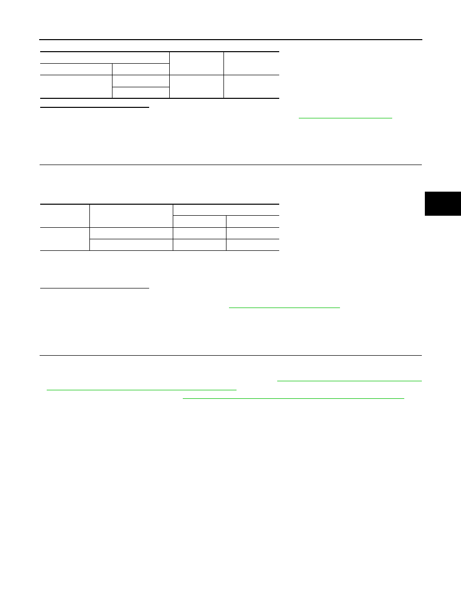
CHECK ACTIVE TEST
1.
Select “ABS”, “ACTIVE TEST” and “ABS MOTOR” in order with CONSULT-III.
2.
Select “On” and “Off” on screen. Make sure motor relay and actuator relay operates as shown in table
below.
NOTE:
A brief moment of On/Off condition occurs every 20 seconds after ignition switch turned ON. This is not malfunction because it is a
operation for checking.
Is the inspection result normal?
YES
>> INSPECTION END
NO
>> Proceed to diagnosis procedure. Refer to
.
Special Repair Requirement
INFOID:0000000005532213
1.
ADJUSTMENT OF STEERING ANGLE SENSOR NEUTRAL POSITION AND CALIBRATION OF DECEL G
SENSOR
After removing/replacing an ABS actuator and electric unit (control unit), be sure to perform the following pro-
cedure.
• Adjustment of steering angle sensor neutral position: Refer to
BRC-9, "ADJUSTMENT OF STEERING
ANGLE SENSOR NEUTRAL POSITION : Description"
.
• Calibration of decel G sensor: Refer to
BRC-10, "CALIBRATION OF DECEL G SENSOR : Description"
.
>> END
ABS actuator and electric unit (control unit)
—
Continuity
Connector
Terminal
E36
13
Ground
Existed
26
Test item
Display item
Display
On
Off
ABS MOTOR
MOTOR RELAY
On
Off
ACTUATOR RLY
On
On
BRC-44
< DTC/CIRCUIT DIAGNOSIS >
[VDC/TCS/ABS]
C1113, C1145, C1146 YAW RATE/SIDE/DECEL G SENSOR
C1113, C1145, C1146 YAW RATE/SIDE/DECEL G SENSOR
Description
INFOID:0000000005517294
Yaw rate/side/decel G sensor detects yaw rate/side/decel G affecting the vehicle, and transmits the data to the
ABS actuator and electric unit (control unit) as an analog voltage signal.
DTC Logic
INFOID:0000000005517295
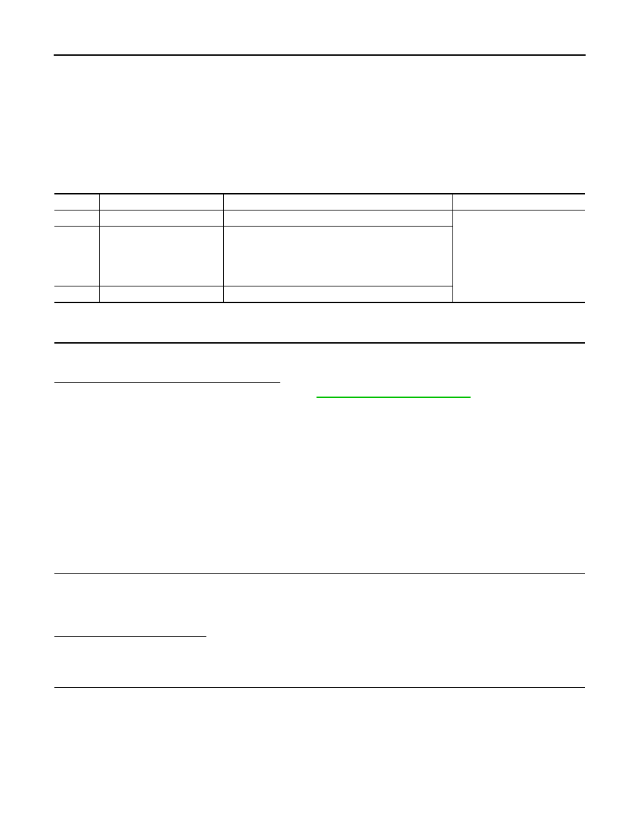
DTC DETECTION LOGIC
DTC CONFIRMATION PROCEDURE
1.
DTC REPRODUCTION PROCEDURE
1.
Turn the ignition switch ON.
2.
Perform self-diagnosis for “ABS” with CONSULT-III.
Is DTC “C1113”, “C1145” or “C1146” detected?
YES
>> Proceed to diagnosis procedure. Refer to
.
NO
>> INSPECTION END
Diagnosis Procedure
INFOID:0000000005517296
CAUTION:
• Sudden turns (such as spin turns, acceleration turns), drifting, etc. may cause yaw rate/side/decel G
sensor circuit indicate a malfunction. However this is not a malfunction if normal operation can be
resumed after restarting engine.
• When on a turntable, such as at a parking structure entrance, or when on a moving object with
engine running, the VDC OFF indicator lamp might turn on and self-diagnosis using the CONSULT-III
yaw rate sensor system malfunction might be displayed, but in this case there is no malfunction with
yaw rate/side/decel G sensor circuit. As soon as the vehicle leaves the turntable or moving object,
restart the engine to return the system to normal.
1.
CHECK CONNECTOR
1.
Turn the ignition switch OFF.
2.
Disconnect ABS actuator and electric unit (control unit) connector.
3.
Disconnect yaw rate/side/decel G sensor connector.
4.
Check terminal for deformation, disconnection, looseness, etc.
Is the inspection result normal?
YES
>> GO TO 2.
NO
>> Replace or repair error-detected parts.
2.
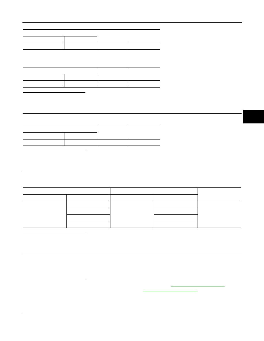
CHECK YAW RATE/SIDE/DECEL G SENSOR POWER SUPPLY CIRCUIT
1.
Turn the ignition switch ON.
CAUTION:
Never start the engine.
2.
Check the voltage between yaw rate/side/decel G sensor harness connector and ground.
DTC
Display item
Malfunction detected condition
Possible cause
C1113
G SENSOR
Decel G sensor is malfunctioning.
• Harness or connector
• ABS actuator and electric unit
(control unit)
• Yaw rate/side/decel G sensor
C1145
YAW RATE SENSOR
• Yaw rate sensor is malfunctioning.
• Yaw rate/side/decel G sensor power voltage is outside
the standard.
• Yaw rate/side/decel G sensor signal line is open or
shorted.
C1146
SIDE G-SEN CIRCUIT
Side G sensor is malfunctioning.
C1113, C1145, C1146 YAW RATE/SIDE/DECEL G SENSOR
BRC-45
< DTC/CIRCUIT DIAGNOSIS >
[VDC/TCS/ABS]
C
D
E
G
H
I
J
K
L
M
A
B
BRC
N
O
P
3.
Turn the ignition switch OFF.
4.
Check the voltage between yaw rate/side/decel G sensor harness connector and ground.
Is the inspection result normal?
YES
>> GO TO 3.
NO
>> Repair or replace error-detected parts.
3.
CHECK YAW RATE/SIDE/DECEL G SENSOR GROUND CIRCUIT
Check the continuity between yaw rate/side/decel G sensor harness connector and ground.
Is the inspection result normal?
YES
>> GO TO 4.
NO
>> Repair or replace error-detected parts.
4.
CHECK YAW RATE/SIDE/DECEL G SENSOR HARNESS
Check the continuity between yaw rate/side/decel G sensor harness connector and ABS actuator and electric
unit (control unit) harness connector.
Is the inspection result normal?
YES
>> GO TO 5.
NO
>> Repair or replace error-detected parts.
5.
CHECK DATA MONITOR
1.
Connect yaw rate/side/decel G sensor harness connector.
2.
Connect ABS actuator and electric unit (control unit) harness connector.
3.
Select “ABS”and “DATA MONITOR” in order with CONSULT-III, select “YAW RATE SEN”, “SIDE G-SEN”
and “DECEL G-SEN”, and check yaw rate/side/decel G sensor signal.
Is the inspection result normal?
YES
>> Replace ABS actuator and electric unit (control unit). Refer to
.
NO
>> Replace yaw rate/side/decel G sensor. Refer to
Component Inspection
INFOID:0000000005517297
1.
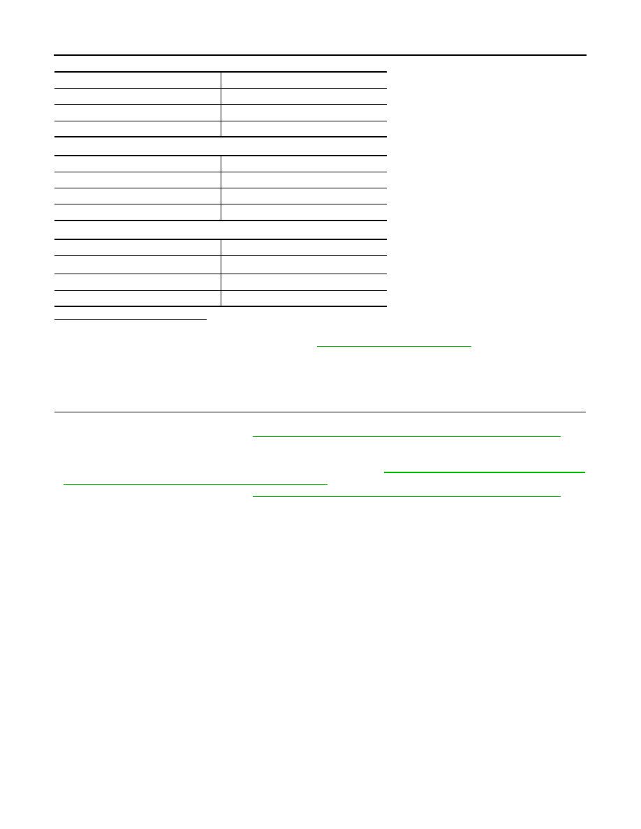
CHECK DATA MONITOR
Select “ABS”and “DATA MONITOR” in order with CONSULT-III, select “YAW RATE SEN”, “SIDE G-SEN” and
“DECEL G-SEN”, and check yaw rate/side/decel G sensor signal.
Yaw rate/side/decel G sensor
—
Voltage
Connector
Terminal
M52
4
Ground
Battery voltage
Yaw rate/side/decel G sensor
—
Voltage
Connector
Terminal
M52
4
Ground
Approx. 0 V
Yaw rate/side/decel G sensor
—
Continuity
Connector
Terminal
M52
1
Ground
Existed
ABS actuator and electric unit (control unit)
Yaw rate/side/decel G sensor
Continuity
Connector
Terminal
Connector
Terminal
E36
25
M52
2
Existed
19
3
4
4
10
1
BRC-46
< DTC/CIRCUIT DIAGNOSIS >
[VDC/TCS/ABS]
C1113, C1145, C1146 YAW RATE/SIDE/DECEL G SENSOR
DECEL G SENSOR
YAW RATE SENSOR
SIDE G SENSOR
Is the inspection result normal?
YES
>> INSPECTION END
NO
>> Proceed to diagnosis procedure. Refer to
.
Special Repair Requirement
INFOID:0000000005517298
1.
ADJUSTMENT OF STEERING ANGLE SENSOR NEUTRAL POSITION AND CALIBRATION OF DECEL G
SENSOR
• After removing/replacing a yaw rate/side/decel G sensor, be sure to perform the following procedure.
- Calibration of decel G sensor: Refer to
BRC-10, "CALIBRATION OF DECEL G SENSOR : Description"
.
• After removing/replacing an ABS actuator and electric unit (control unit), be sure to perform the following
procedure.
- Adjustment of steering angle sensor neutral position: Refer to
BRC-9, "ADJUSTMENT OF STEERING
ANGLE SENSOR NEUTRAL POSITION : Description"
.
- Calibration of decel G sensor: Refer to
BRC-10, "CALIBRATION OF DECEL G SENSOR : Description"
.
>> END
Vehicle condition
DATA MONITOR
Vehicle stopped
Approx. 0 G
Vehicle acceleration
Positive value
Vehicle deceleration
Negative value
Vehicle condition
DATA MONITOR
Vehicle stopped
Approx. 0 d/s
Vehicle turning right
Negative value
Vehicle turning left
Positive value
Vehicle condition
DATA MONITOR
Vehicle stopped
Approx. 0 m/s
2
Vehicle turning right
Negative value
Vehicle turning left
Positive value
Нет комментариевНе стесняйтесь поделиться с нами вашим ценным мнением.
Текст