Nissan Murano Z51. Instruction — part 564
EC-264
< DTC/CIRCUIT DIAGNOSIS >
[VQ35DE]
P0420, P0430 THREE WAY CATALYST FUNCTION
Is the inspection result normal?
YES
>> INSPECTION END
NO
>> Go to
Diagnosis Procedure
INFOID:0000000005536663
1.
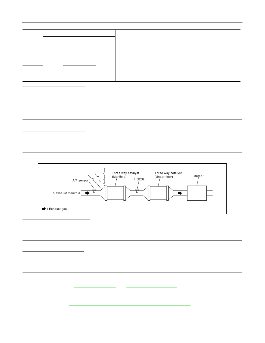
CHECK EXHAUST SYSTEM
Visually check exhaust tubes and muffler for dents.
Is the inspection result normal?
YES
>> GO TO 2.
NO
>> Repair or replace malfunctioning part.
2.
CHECK EXHAUST GAS LEAKAGE
1.
Start engine and run it at idle.
2.
Listen for an exhaust gas leakage before the three way catalyst (manifold).
Is exhaust gas leakage detected?
YES
>> Repair or replace malfunctioning part.
NO
>> GO TO 3.
3.
CHECK INTAKE AIR LEAKAGE
Listen for an intake air leakage after the mass air flow sensor.
Is intake air leakage detected?
YES
>> Repair or replace malfunctioning part.
NO
>> GO TO 4.
4.
CHECK IGNITION TIMING
Check idle speed and ignition timing.
For procedure, refer to
EC-13, "BASIC INSPECTION : Special Repair Requirement"
For specification, refer to
.
Is the inspection result normal?
YES
>> GO TO 5.
NO
>> Follow the
EC-13, "BASIC INSPECTION : Special Repair Requirement"
5.
CHECK FUEL INJECTORS
1.
Stop engine and then turn ignition switch ON.
2.
Check the voltage between ECM harness connector terminals.
DTC
ECM
Condition
Voltage (V)
Connec-
tor
+
–
Terminal
Terminal
P0420
F8
33
[HO2S2 (bank 1)
signal]
35
(Sensor
ground)
Keeping engine speed at 2,500 rpm
constant under no load
The voltage fluctuation cycle takes
more than 5 seconds.
• 1 cycle: 0.6 - 1.0
→
0 - 0.3
→
0.6 -
1.0
P0430
34
[HO2S2 (bank 2)
signal]
PBIB1216E
P0420, P0430 THREE WAY CATALYST FUNCTION
EC-265
< DTC/CIRCUIT DIAGNOSIS >
[VQ35DE]
C
D
E
F
G
H
I
J
K
L
M
A
EC
N
P
O
Is the inspection result normal?
YES
>> GO TO 6.
NO
>> Perform
.
6.
CHECK FUNCTION OF IGNITION COIL-I
CAUTION:
Perform the following procedure in a place with no combustible objects and good ventilation.
1.
Turn ignition switch OFF.
2.
Remove fuel pump fuse in IPDM E/R to release fuel pressure.
NOTE:
Do not use CONSULT-III to release fuel pressure, or fuel pressure applies again during the following pro-
cedure.
3.
Start engine.
4.
After engine stalls, crank it 2 or 3 times to release all fuel pressure.
5.
Turn ignition switch OFF.
6.
Remove all ignition coil harness connectors to avoid the electrical discharge from the ignition coils.
7.
Remove ignition coil and spark plug of the cylinder to be checked.
8.
Crank engine for 5 seconds or more to remove combustion gas in the cylinder.
9.
Connect spark plug and harness connector to ignition coil.
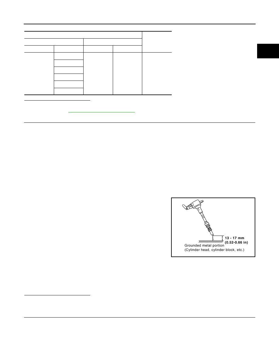
10. Fix ignition coil using a rope etc. with gap of 13 - 17 mm (0.52 -
0.66 in) between the edge of the spark plug and grounded metal
portion as shown in the figure.
11. Crank engine for approximately 3 seconds, and check whether
spark is generated between the spark plug and the grounded
metal portion.
CAUTION:
• During the operation, always stay 0.5 m (19.7 in) or more
away from the spark plug and the ignition coil. Be careful
not to get an electrical shock while checking, because the
electrical discharge voltage becomes 20 kV or more.
• It might cause to damage the ignition coil if the gap of more than 17 mm (0.66 in) is taken.
NOTE:
When the gap is less than 13 mm (0.52 in), the spark might be generated even if the coil is mal-
functioning.
Is the inspection result normal?
YES
>> GO TO 10.
NO
>> GO TO 7.
7.
CHECK FUNCTION OF IGNITION COIL-II
1.
Turn ignition switch OFF.
2.
Disconnect spark plug and connect a known-good spark plug.
3.
Crank engine for approximately 3 seconds, and recheck whether spark is generated between the spark
plug and the grounded metal portion.
ECM
Voltage
+
–
Connector
Terminal
Connector
Terminal
F7
1
E16
112
Battery voltage
3
29
30
31
32
Spark should be generated.
JMBIA0066GB
EC-266
< DTC/CIRCUIT DIAGNOSIS >
[VQ35DE]
P0420, P0430 THREE WAY CATALYST FUNCTION
Is the inspection result normal?
YES
>> GO TO 8.
NO
>> Check ignition coil, power transistor and their circuit. Refer to
8.
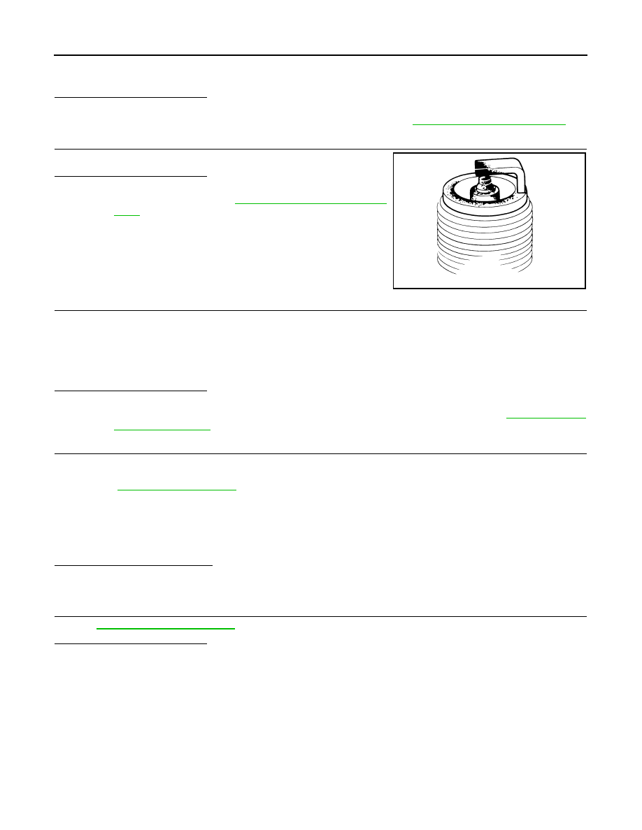
CHECK SPARK PLUG
Check the initial spark plug for fouling, etc.
Is the inspection result normal?
YES
>> Replace spark plug(s) with standard type one(s). For
spark plug type, refer to
.
NO
>> Repair or clean spark plug. Then GO TO 9.
9.
CHECK FUNCTION OF IGNITION COIL-III
1.
Reconnect the initial spark plugs.
2.
Crank engine for approximately 3 seconds, and recheck whether spark is generated between the spark
plug and the grounded portion.
Is the inspection result normal?
YES
>> INSPECTION END
NO
>> Replace spark plug(s) with standard type one(s). For spark plug type, refer to
10.
CHECK FUEL INJECTOR
1.
Turn ignition switch OFF.
2.
Remove fuel injector assembly.
Refer to
Keep fuel hose and all fuel injectors connected to fuel tube.
3.
Disconnect all ignition coil harness connectors.
4.
Reconnect all fuel injector harness connectors disconnected.
5.
Turn ignition switch ON.
6.
Check that the fuel does not drip from fuel injector.
Does fuel drip from fuel injector?
YES
>> Replace the fuel injector(s) from which fuel is dripping.
NO
>> GO TO 11.
11.
CHECK INTERMITTENT INCIDENT
GI-39, "Intermittent Incident"
Is the inspection result normal?
YES
>> Replace three way catalyst assembly.
NO
>> Repair or replace harness or connector.
Spark should be generated.
SEF156I
Spark should be generated.
P0441 EVAP CONTROL SYSTEM
EC-267
< DTC/CIRCUIT DIAGNOSIS >
[VQ35DE]
C
D
E
F
G
H
I
J
K
L
M
A
EC
N
P
O
P0441 EVAP CONTROL SYSTEM
DTC Logic
INFOID:0000000005536664
DTC DETECTION LOGIC
NOTE:
If DTC P0441 is displayed with other DTC such as P2122, P2123, P2127, P2128 or P2138, first perform
trouble diagnosis for other DTC.
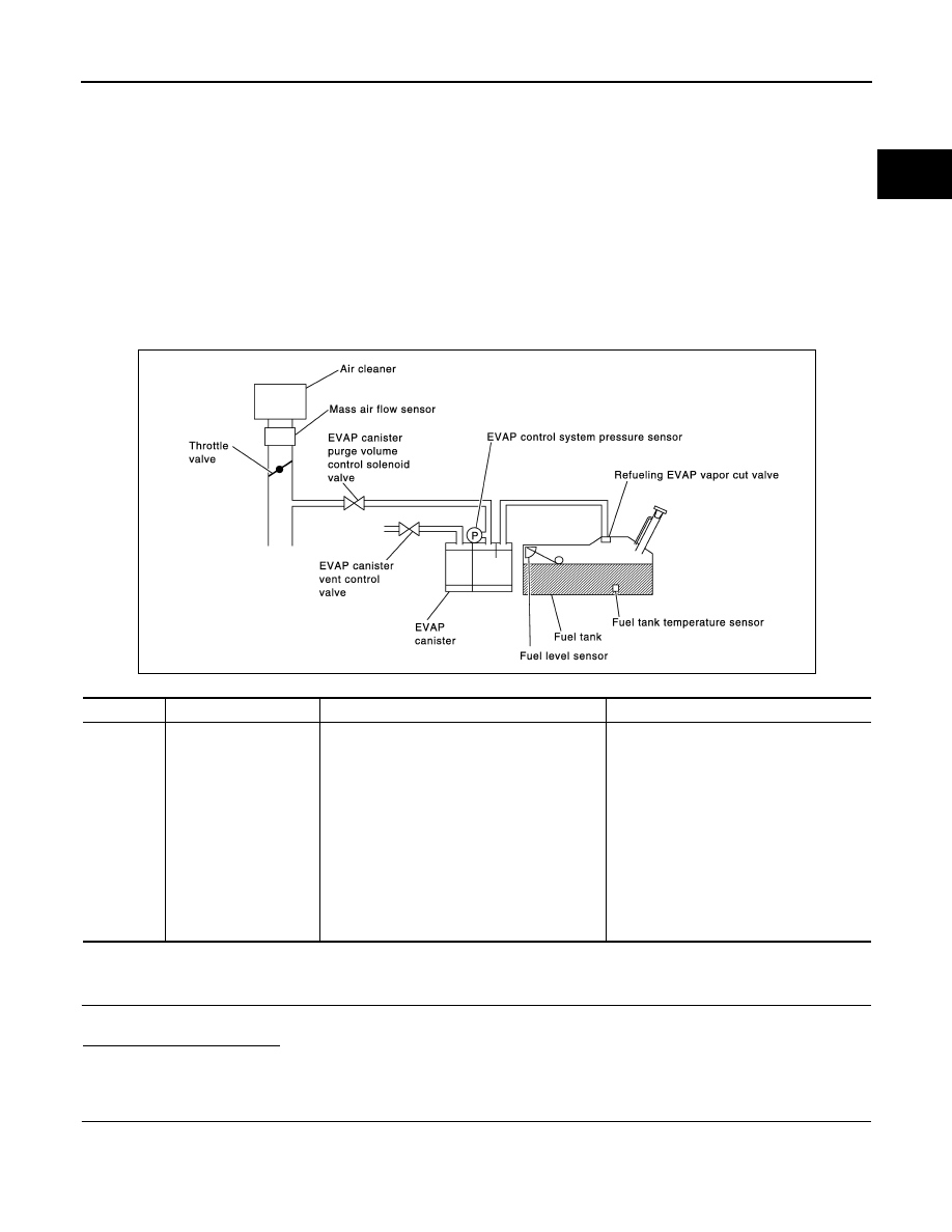
In this evaporative emission (EVAP) control system, purge flow occurs during non-closed throttle conditions.
Purge volume is related to air intake volume. Under normal purge conditions (non-closed throttle), the EVAP
canister purge volume control solenoid valve is open to admit purge flow. Purge flow exposes the EVAP con-
trol system pressure sensor to intake manifold vacuum.
Under normal conditions (non-closed throttle), sensor output voltage indicates if pressure drop and purge flow
are adequate. If not, a malfunction is determined.
DTC CONFIRMATION PROCEDURE
1.
INSPECTION START
Will CONSULT-III be used?
Will CONSULT-III be used?
YES
>> GO TO 2.
NO
>> GO TO 6.
2.
PRECONDITIONING
If DTC Confirmation Procedure has been previously conducted, always perform the following before conduct-
ing the next test.
1.
Turn ignition switch OFF and wait at least 10 seconds.
DTC No.
Trouble diagnosis name
DTC detecting condition
Possible cause
P0441
EVAP control system in-
correct purge flow
EVAP control system does not operate proper-
ly, EVAP control system has a leakage between
intake manifold and EVAP control system pres-
sure sensor.
• EVAP canister purge volume control so-
lenoid valve stuck closed
• EVAP control system pressure sensor
and the circuit
• Loose, disconnected or improper con-
nection of rubber tube
• Blocked rubber tube
• Cracked EVAP canister
• EVAP canister purge volume control so-
lenoid valve circuit
• Accelerator pedal position sensor
• Blocked purge port
• EVAP canister vent control valve
PBIB1026E
Нет комментариевНе стесняйтесь поделиться с нами вашим ценным мнением.
Текст