Nissan Murano Z51. Instruction — part 353

DIAGNOSIS AND REPAIR WORKFLOW
DEF-3
< BASIC INSPECTION >
C
D
E
F
G
H
I
J
K
M
A
B
DEF
N
O
P
BASIC INSPECTION
DIAGNOSIS AND REPAIR WORKFLOW
Work Flow
INFOID:0000000005513185
DETAILED FLOW
1.
OBTAIN INFORMATION ABOUT SYMPTOM
Interview the customer to obtain the malfunction information (conditions and environment when the malfunc-
tion occurred) as much as possible when the customer brings the vehicle in.
>> GO TO 2.
2.
CHECK DTC
Perform self diagnosis with CONSULT-III
Is any DTC detected?
YES
>> Refer to
NO
>> GO TO 3.
3.
REPRODUCE THE MALFUNCTION INFORMATION
Check the malfunction on the vehicle that the customer describes.
Inspect the relation of the symptoms and the condition when the symptoms occur.
>> GO TO 4.
4.
IDENTIFY THE MALFUNCTIONING SYSTEM WITH “SYMPTOM DIAGNOSIS”
Use “Symptom diagnosis” from the symptom inspection result in step 3. Then identify where to start perform-
ing the diagnosis based on possible causes and symptoms.
>> GO TO 5.
5.
IDENTIFY MALFUNCTIONING PARTS WITH “COMPONENT DIAGNOSIS”
Perform the diagnosis with “Component diagnosis” of the applicable system.
>> GO TO 6.
6.
REPAIR OR REPLACE THE MALFUNCTIONING PARTS
Repair or replace the specified malfunctioning parts.
>> GO TO 7.
7.
FINAL CHECK
Check that malfunctions are not reproduced when obtaining the malfunction information from the customer,
referring to the symptom inspection result in step 3.
Are all malfunctions corrected?
YES
>> INSPECTION END
NO
>> GO TO 4.
DEF-4
< SYSTEM DESCRIPTION >
REAR WINDOW DEFOGGER SYSTEM
SYSTEM DESCRIPTION
REAR WINDOW DEFOGGER SYSTEM
WITH BOSE SYSTEM
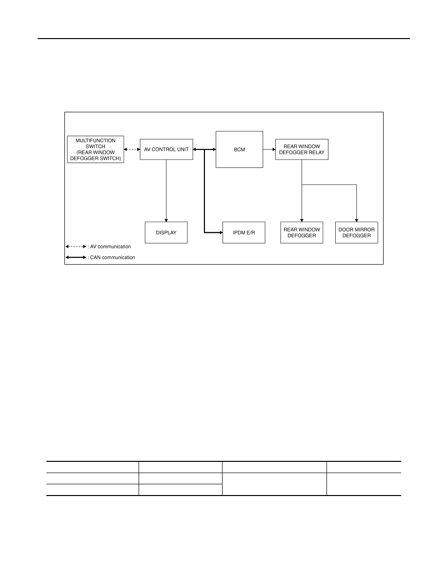
WITH BOSE SYSTEM : System Diagram
INFOID:0000000005513186
WITH BOSE SYSTEM : System Description
INFOID:0000000005513187
Operation Description
• Turn rear window defogger switch ON when the ignition switch is turned ON. Then multifunction switch (rear
window defogger switch) transmits rear window defogger switch signal to AV control unit via AV communica-
tion. AV control unit transmits rear window defogger switch signal to BCM via CAN communication.
• BCM turns rear window defogger relay ON and transmits rear window defogger control signal to IPDM E/R
via CAN communication when rear window defogger switch signal is received.
• Rear window defogger and door mirror defogger (with door mirror defogger) are supplied with power and
operate when rear window defogger relay turns ON.
• IPDM E/R transmits rear window defogger control signal to AV control unit via CAN communication.
• AV control unit transmit rear defogger indicator signal to multifunction switch (rear window defogger switch)
via AV communication. then rear window defogger indicator is illuminated.
Timer function
• BCM turns rear window defogger relay ON for approximately 15 minutes when rear window defogger switch
is turned ON. It makes rear window defogger and door mirror defogger (with door mirror defogger) operate.
• Timer is canceled after pressing rear window defogger switch again during timer operation. Then BCM turns
rear window defogger relay OFF. The same reaction also occurs during timer operation, if the ignition switch
is turned OFF.
INPUT/OUTPUT SIGNAL CHART
*: With door mirror defogger
JMLIA0005GB
Switch
Input signal to BCM
BCM function
Actuator
Rear window defogger switch
Defogger switch signal
Rear window defogger & Door mir-
ror defogger
*
control
Rear window defogger
Door mirror defogger
*
Push button ignition switch
Ignition signal
REAR WINDOW DEFOGGER SYSTEM
DEF-5
< SYSTEM DESCRIPTION >
C
D
E
F
G
H
I
J
K
M
A
B
DEF
N
O
P
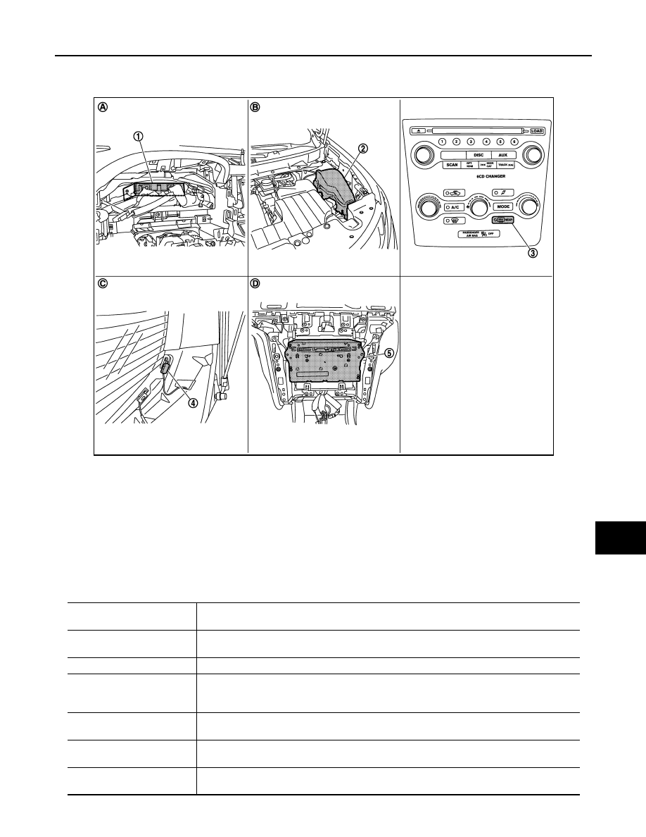
WITH BOSE SYSTEM : Component Parts Location
INFOID:0000000005513188
WITH BOSE SYSTEM : Component Description
INFOID:0000000005513189
1.
BCM M118, M119, M122, M123
2.
IPDM E/R E6, E11
3.
Rear window defogger switch
(built-in multifunction switch M125)
4.
Rear window defogger connector
D184
5.
AV control unit
With NAVI M145, M146
Without NAVI M129, M131
A.
Dash side lower (passenger side)
B.
Engine room dash panel (LH)
C.
Behind rear pillar finisher (LH)
D.
Behind cluster lid C
JMLIA0119ZZ
BCM
• Operates the rear window defogger with the operation of rear window defogger switch.
• Performs the timer control of rear window defogger.
Rear window defogger relay
• Operates the rear window defogger and the door mirror defogger with the control signal from
BCM.
IPDM E/R
• Transmit rear window defogger control signal to AV control unit via CAN communication.
Multifunction switch
(Rear window defogger
switch)
• The rear window defogger switch is installed.
• Turns the indicator lamp ON when detecting the operation of rear window defogger.
AV control unit
• Displays the rear window defogger ON to the display when detecting the operation of rear win-
dow defogger.
Rear window defogger
• Heats the heating wire with the power supply from the rear window defogger relay to prevent
the rear window from fogging up.
Door mirror defogger
*
• Heats the heating wire with the power supply from the rear window defogger relay to prevent
the door mirror from fogging up.
DEF-6
< SYSTEM DESCRIPTION >
REAR WINDOW DEFOGGER SYSTEM
*:
With mirror defogger
WITHOUT BOSE SYSTEM
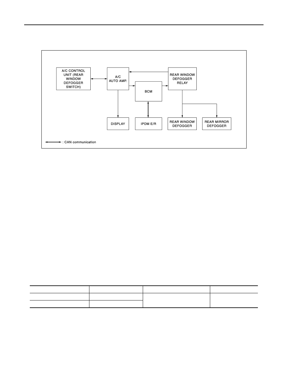
WITHOUT BOSE SYSTEM : System Diagram
INFOID:0000000005513190
WITHOUT BOSE SYSTEM : System Description
INFOID:0000000005513191
Operation Description
• Turn rear window defogger switch ON when the ignition switch is turned ON. Then A/C control unit (rear win-
dow defogger switch) transmits rear window defogger switch signal to A/C auto amp.. transmits rear window
defogger switch signal to BCM.
• BCM turns rear window defogger relay ON and transmits rear window defogger control signal to IPDM E/R
via CAN communication when rear window defogger switch signal is received.
• Rear window defogger and door mirror defogger (with door mirror defogger) are supplied with power and
operate when rear window defogger relay turns ON.
• Rear window defogger relay transmits rear window defogger control signal to A/C auto amp. when rear win-
dow defogger operates.
• A/C auto amp. transmit rear window defogger indicator signal to A/C control unit (rear window defogger
switch). Then rear window defogger indicator is illuminated.
Timer function
• BCM turns rear window defogger relay ON for approximately 15 minutes when rear window defogger switch
is turned ON. It makes rear window defogger and door mirror defogger (with door mirror defogger) operate.
• Timer is canceled after pressing rear window defogger switch again during timer operation. Then BCM turns
rear window defogger relay OFF. The same reaction also occurs during timer operation, if the ignition switch
is turned OFF.
INPUT/OUTPUT SIGNAL CHART
*: With door mirror defogger
JMLIA0127GB
Switch
Input signal to BCM
BCM function
Actuator
Rear window defogger switch
Defogger switch signal
Rear window defogger & Door mir-
ror defogger
*
control
Rear window defogger
Door mirror defogger
*
Push button ignition switch
Ignition signal
Нет комментариевНе стесняйтесь поделиться с нами вашим ценным мнением.
Текст