Nissan Murano Z51. Instruction — part 351
WATER PUMP
CO-25
< REMOVAL AND INSTALLATION >
C
D
E
F
G
H
I
J
K
L
M
A
CO
N
P
O
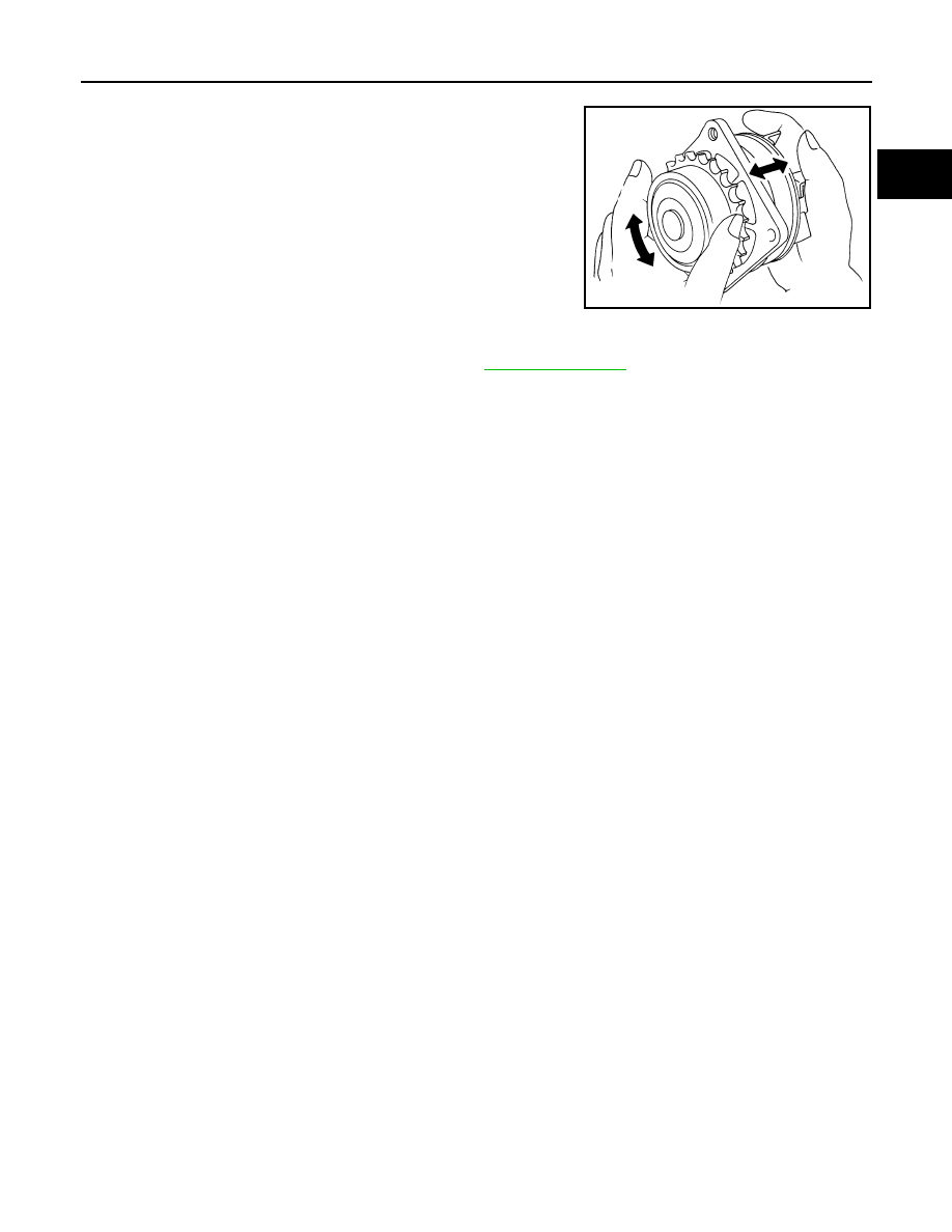
• Check for badly rusted or corroded water pump body assembly.
• Check for rough operation due to excessive end play.
• If anything is found, replace water pump.
INSPECTION AFTER INSTALLATION
• Check for leakage of engine coolant using the radiator cap tester adapter (commercial service tool) and the
radiator cap tester (commercial service tool). Refer to
• Start and warm up the engine. Visually check that there is no leakage of engine coolant.
SLC943A
CO-26
< REMOVAL AND INSTALLATION >
WATER INLET AND THERMOSTAT ASSEMBLY
WATER INLET AND THERMOSTAT ASSEMBLY
Exploded View
INFOID:0000000005518106
Removal and Installation
INFOID:0000000005518107
REMOVAL
1.
Drain engine coolant from radiator drain plug at the bottom of radiator, and from water drain plug at the
front of cylinder block. Refer to
CAUTION:
• Perform this step when the engine is cold.
• Never spill engine coolant on drive belt.
2.
Remove reservoir tank of radiator, and move it aside. Refer to
.
3.
Remove intake valve timing control solenoid valve (bank 2). Refer to
.
4.
Disconnect radiator hose (lower) from water inlet and thermostat assembly.
5.
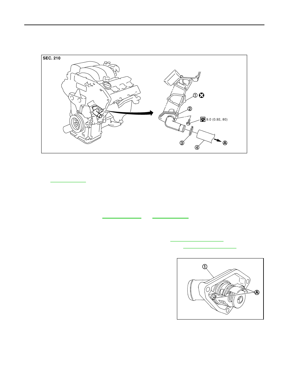
Remove water inlet and thermostat assembly (1).
CAUTION:
Never disassemble water inlet and thermostat assembly.
Replace them as a unit, if necessary.
INSTALLATION
Note the following, and install in the reverse order of removal.
• Be careful not to spill engine coolant over engine room. Use rag to absorb engine coolant.
1.
Gasket
2.
Water inlet and thermostat assembly
3.
Clamp
4.
Radiator hose (lower)
A.
To radiator
Refer to
for symbols in the figure.
JPBIA1688GB
A
: Never loosen these screw
JPBIA0261ZZ
WATER INLET AND THERMOSTAT ASSEMBLY
CO-27
< REMOVAL AND INSTALLATION >
C
D
E
F
G
H
I
J
K
L
M
A
CO
N
P
O
Inspection
INFOID:0000000005518108
INSPECTION AFTER REMOVAL
1.
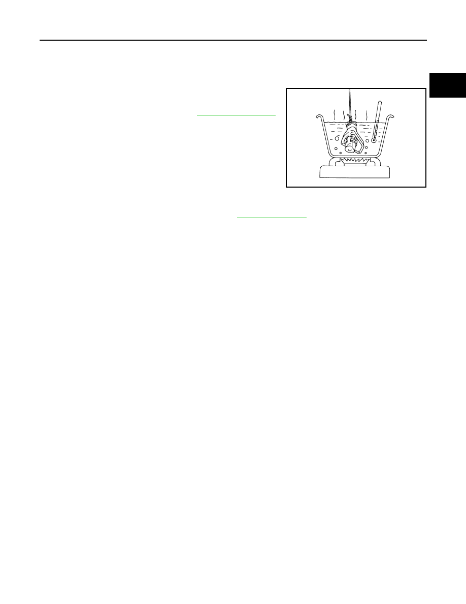
Check valve seating condition at ordinary room temperatures. It should seat tightly.
2.
Check valve operation.
• If the malfunctioning condition, when valve seating at ordinary
room temperature, or measured values are out of the standard,
replace water inlet and thermostat assembly.
INSPECTION AFTER INSTALLATION
• Check for leakage of engine coolant using the radiator cap tester adapter (commercial service tool) and the
radiator cap tester (commercial service tool). Refer to
• Start and warm up the engine. Visually check that there is no leakage of engine coolant.
Thermostat (Standard)
: Refer to
.
SLC949A
CO-28
< REMOVAL AND INSTALLATION >
WATER OUTLET AND WATER PIPING
WATER OUTLET AND WATER PIPING
Exploded View
INFOID:0000000005518109
Removal and Installation
INFOID:0000000005518110
REMOVAL
1.
Remove air duct (inlet), radiator core support covers (RH and LH), air cleaner cases (upper and lower)
with mass air flow sensor and air duct assembly. Refer to
2.
Remove engine cover. Refer to
3.
Drain engine coolant from radiator drain plug at the bottom of radiator, and from water drain plug at the
front of cylinder block. Refer to
CAUTION:
• Perform this step when the engine is cold.
• Never spill engine coolant on drive belt.
4.
Remove battery and battery tray. Refer to
PG-119, "Removal and Installation"
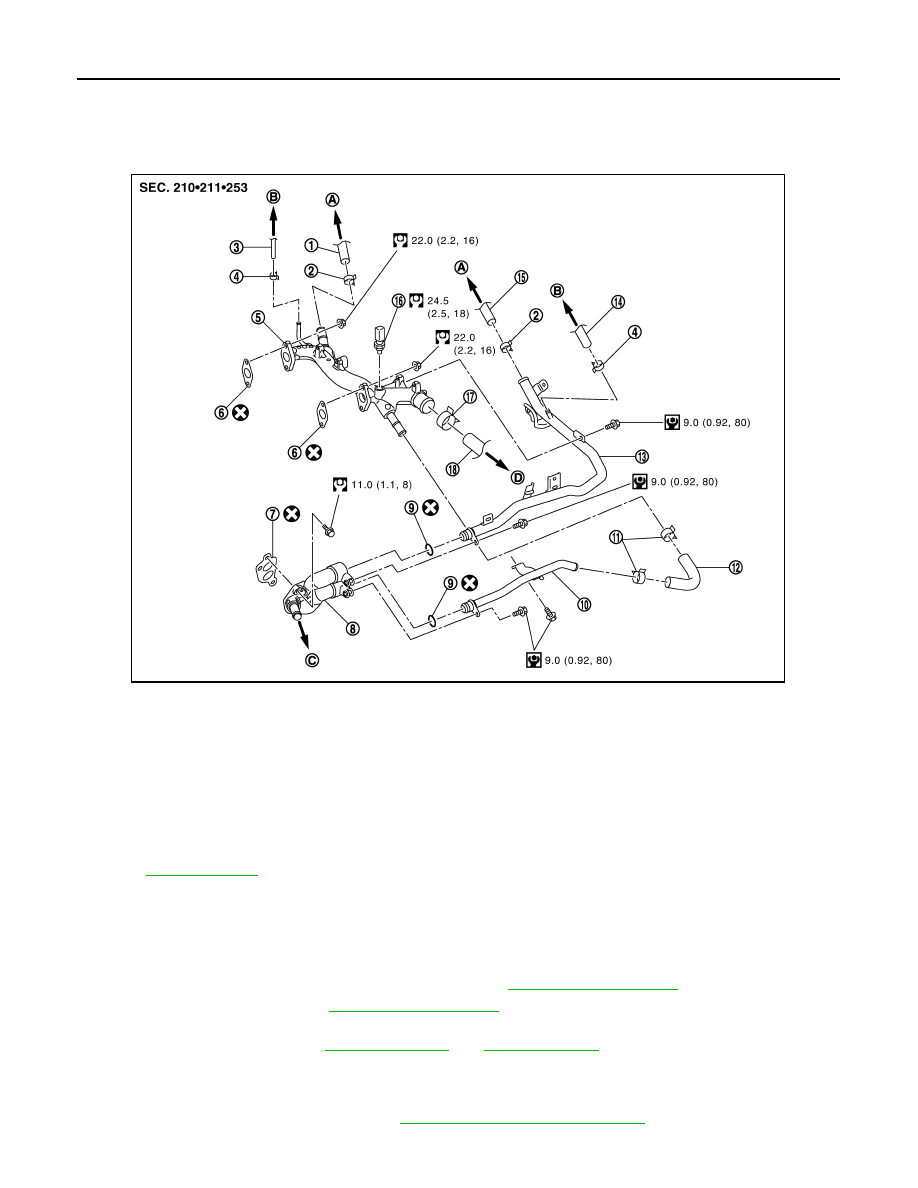
1.
Heater hose
2.
Clamp
3.
Water hose
4.
Clamp
5.
Water outlet
6.
Gasket
7.
Gasket
8.
Water connector
9.
O-ring
10. Water bypass pipe
11.
Clamp
12.
Water hose
13. Heater pipe
14.
Water hose
15.
Heater hose
16. Engine coolant temperature sensor
17.
Clamp
18.
Radiator hose (upper)
A.
To heater core
B.
To electric throttle control actuator
C.
To oil cooler
D.
To radiator
Refer to
for symbols in the figure.
JPBIA1691GB
Нет комментариевНе стесняйтесь поделиться с нами вашим ценным мнением.
Текст