Nissan Murano Z51. Instruction — part 777
FAX-1
TRANSMISSION & DRIVELINE
C
E
F
G
H
I
J
K
L
M
SECTION
FAX
A
B
FAX
N
O
P
CONTENTS
FRONT AXLE
2WD
SYMPTOM DIAGNOSIS . . . . . . . ...
NOISE, VIBRATION AND HARSHNESS
(NVH) TROUBLESHOOTING . . . . . . . .
NVH Troubleshooting Chart . . . . . . . . . ..
PRECAUTION . . . . . . . . . . . ...
PRECAUTIONS . . . . . . . . . . . . ...
FOR USA AND CANADA . . . . . . . . . . ....
FOR USA AND CANADA : Precautions for Drive
Shaft . . . . . . . . . . . . . . . . . . ..
FOR MEXICO . . . . . . . . . . . . . . . ..
FOR MEXICO : Precaution Necessary for Steer-
ing Wheel Rotation after Battery Disconnect . . ....
FOR MEXICO : Precautions for Drive Shaft . . .....
PREPARATION . . . . . . . . . . .
PREPARATION . . . . . . . . . . . . ...
Special Service Tool . . . . . . . . . . . .....
Commercial Service Tool . . . . . . . . . . ..
PERIODIC MAINTENANCE . . . . . . ..
FRONT WHEEL HUB AND KNUCKLE . . . ..
Inspection . . . . . . . . . . . . . . . . ..
FRONT DRIVE SHAFT . . . . . . . . . .
Inspection . . . . . . . . . . . . . . . . ..
REMOVAL AND INSTALLATION . . . ...
FRONT WHEEL HUB AND KNUCKLE . . .
Exploded View . . . . . . . . . . . . . . .
Removal and Installation . . . . . . . . . . .
Inspection . . . . . . . . . . . . . . . .
FRONT DRIVE SHAFT BOOT . . . . . . ..
Exploded View . . . . . . . . . . . . . . .
WHEEL SIDE . . . . . . . . . . . . . . . .
WHEEL SIDE : Removal and Installation . . . .
TRANSAXLE SIDE . . . . . . . . . . . . .
TRANSAXLE SIDE : Removal and Installation . ...
Inspection . . . . . . . . . . . . . . . .
FRONT DRIVE SHAFT . . . . . . . . . .
Exploded View . . . . . . . . . . . . . . .
LEFT SIDE . . . . . . . . . . . . . . . . .
LEFT SIDE : Removal and Installation . . . . .
RIGHT SIDE . . . . . . . . . . . . . . . ...
RIGHT SIDE : Removal and Installation . . . . ..
WHEEL SIDE . . . . . . . . . . . . . . . .
WHEEL SIDE : Disassembly and Assembly . . ...
TRANSAXLE SIDE . . . . . . . . . . . . .
TRANSAXLE SIDE : Disassembly and Assembly
Inspection . . . . . . . . . . . . . . . .
SERVICE DATA AND SPECIFICATIONS
(SDS) . . . . . . . . . . . . . . .
SERVICE DATA AND SPECIFICATIONS
(SDS) . . . . . . . . . . . . . . . . .
Wheel Bearing . . . . . . . . . . . . . . .
Drive Shaft . . . . . . . . . . . . . . . ...
AWD
FAX-2
NOISE, VIBRATION AND HARSHNESS
(NVH) TROUBLESHOOTING . . . . . . .
NVH Troubleshooting Chart . . . . . . . . ...
PRECAUTION . . . . . . . . . . . .
PRECAUTIONS . . . . . . . . . . . . .
FOR USA AND CANADA . . . . . . . . . . .
FOR USA AND CANADA : Precautions for Drive
Shaft . . . . . . . . . . . . . . . . . ...
FOR MEXICO . . . . . . . . . . . . . . ....
FOR MEXICO : Precaution Necessary for Steer-
ing Wheel Rotation after Battery Disconnect . . ..
FOR MEXICO : Precautions for Drive Shaft . . ...
PREPARATION . . . . . . . . . . ...
PREPARATION . . . . . . . . . . . . .
Special Service Tool . . . . . . . . . . . ...
Commercial Service Tool . . . . . . . . . ...
PERIODIC MAINTENANCE . . . . . .
FRONT WHEEL HUB AND KNUCKLE . . . .
Inspection . . . . . . . . . . . . . . . ...
FRONT DRIVE SHAFT . . . . . . . . . ..
Inspection . . . . . . . . . . . . . . . ...
REMOVAL AND INSTALLATION . . . ..
FRONT WHEEL HUB AND KNUCKLE . . . .
Exploded View . . . . . . . . . . . . . .
Removal and Installation . . . . . . . . . . .
Inspection . . . . . . . . . . . . . . . .
FRONT DRIVE SHAFT BOOT . . . . . . ..
Exploded View . . . . . . . . . . . . . .
WHEEL SIDE . . . . . . . . . . . . . . . .
WHEEL SIDE : Removal and Installation . . . ...
TRANSAXLE SIDE . . . . . . . . . . . . .
TRANSAXLE SIDE : Removal and Installation . ...
Inspection . . . . . . . . . . . . . . . .
FRONT DRIVE SHAFT . . . . . . . . . ..
Exploded View . . . . . . . . . . . . . .
LEFT SIDE . . . . . . . . . . . . . . . . .
LEFT SIDE : Removal and Installation . . . . ...
RIGHT SIDE . . . . . . . . . . . . . . . ..
RIGHT SIDE : Removal and Installation . . . . .
WHEEL SIDE . . . . . . . . . . . . . . . .
WHEEL SIDE : Disassembly and Assembly . . ...
TRANSAXLE SIDE . . . . . . . . . . . . .
TRANSAXLE SIDE : Disassembly and Assembly ...
Inspection . . . . . . . . . . . . . . . .
SERVICE DATA AND SPECIFICATIONS
(SDS) . . . . . . . . . . . . . . ..
SERVICE DATA AND SPECIFICATIONS
(SDS) . . . . . . . . . . . . . . . . .
Wheel Bearing . . . . . . . . . . . . . .
NOISE, VIBRATION AND HARSHNESS (NVH) TROUBLESHOOTING
FAX-3
< SYMPTOM DIAGNOSIS >
[2WD]
C
E
F
G
H
I
J
K
L
M
A
B
FAX
N
O
P
SYMPTOM DIAGNOSIS
NOISE, VIBRATION AND HARSHNESS (NVH) TROUBLESHOOTING
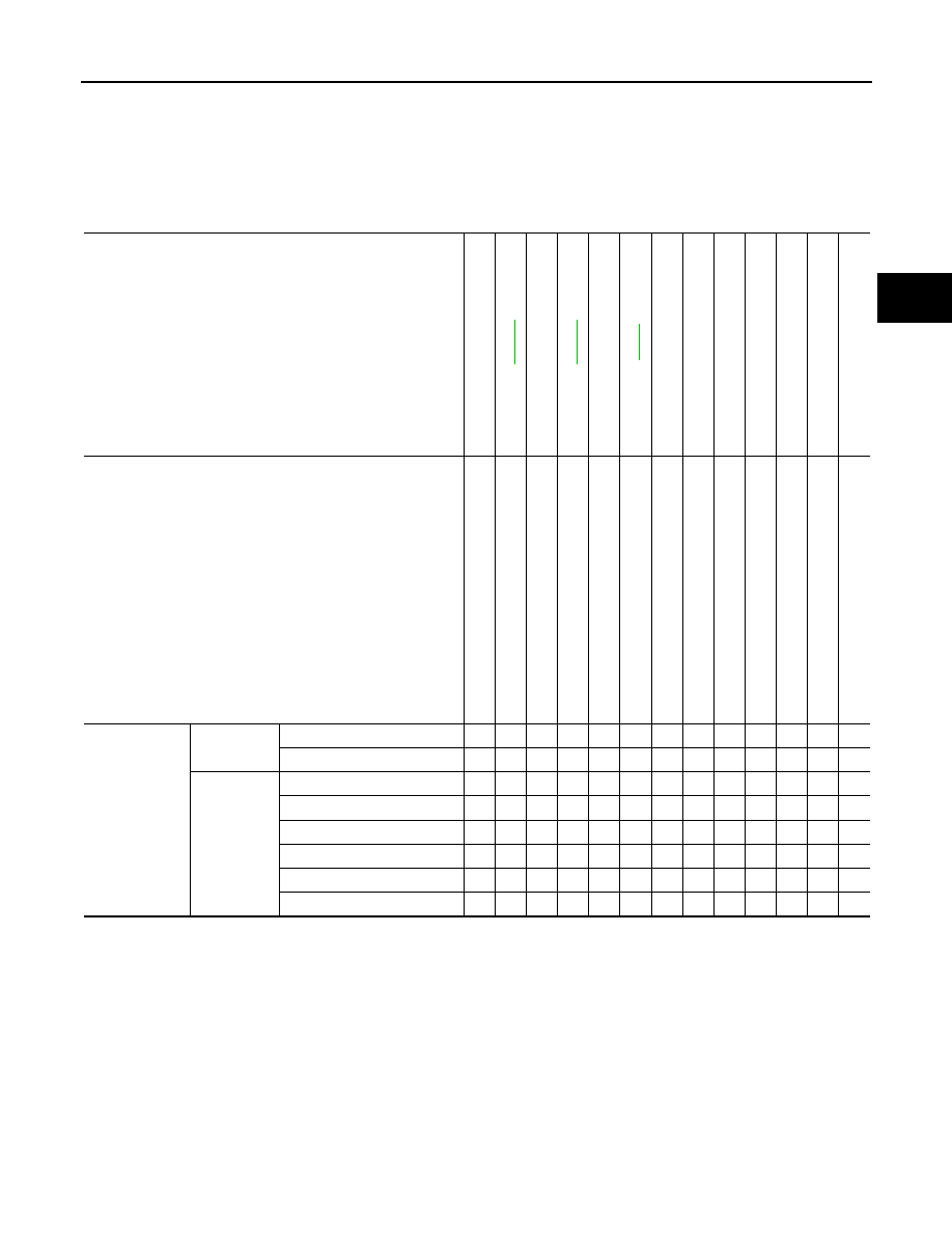
NVH Troubleshooting Chart
INFOID:0000000005518939
Use chart below to find the cause of the symptom. If necessary, repair or replace these parts.
×
: Applicable
Reference page
—
—
—
NV
H in
F
A
X
an
d
FSU s
e
c
tio
ns
Refe
r to
Fro
n
t axle
in
th
is ch
art
NVH in WT
section
NVH in WT
section
Ref
e
r t
o
DRIVE
SHAFT
in this
chart
NVH in BR
section
NVH in S
T
section
Possible cause and SUSPECTED PARTS
Ex
ce
ss
iv
e joi
nt an
gl
e
Jo
in
t sl
id
in
g
re
si
st
a
n
c
e
Im
ba
la
nc
e
Imp
rop
er i
ns
ta
lla
ti
o
n,
lo
os
en
es
s
Part
s interf
erence
Whe
e
l be
ari
n
g
da
ma
ge
FRONT A
X
LE
AND FRONT SUSP
ENSION
FRONT A
XLE
TI
RE
ROAD WHEE
L
DRIVE SHAFT
BRAKE
STE
E
RING
Symptom
DRIVE
SHAFT
Noise
×
×
×
×
×
×
×
×
×
Shake
×
×
×
×
×
×
×
×
×
FRONT
AXLE
Noise
×
×
×
×
×
×
×
×
×
Shake
×
×
×
×
×
×
×
×
×
Vibration
×
×
×
×
×
×
×
Shimmy
×
×
×
×
×
×
×
Judder
×
×
×
×
×
×
Poor quality ride or handling
×
×
×
×
×
FAX-4
< PRECAUTION >
[2WD]
PRECAUTIONS
PRECAUTION
PRECAUTIONS
FOR USA AND CANADA
FOR USA AND CANADA : Precaution for Supplemental Restraint System (SRS) "AIR
BAG" and "SEAT BELT PRE-TENSIONER"
INFOID:0000000005565309
The Supplemental Restraint System such as “AIR BAG” and “SEAT BELT PRE-TENSIONER”, used along
with a front seat belt, helps to reduce the risk or severity of injury to the driver and front passenger for certain
types of collision. This system includes seat belt switch inputs and dual stage front air bag modules. The SRS
system uses the seat belt switches to determine the front air bag deployment, and may only deploy one front
air bag, depending on the severity of a collision and whether the front occupants are belted or unbelted.
Information necessary to service the system safely is included in the “SRS AIR BAG” and “SEAT BELT” of this
Instruction.
WARNING:
• To avoid rendering the SRS inoperative, which could increase the risk of personal injury or death in
the event of a collision which would result in air bag inflation, all maintenance must be performed by
an authorized NISSAN/INFINITI dealer.
• Improper maintenance, including incorrect removal and installation of the SRS, can lead to personal
injury caused by unintentional activation of the system. For removal of Spiral Cable and Air Bag
Module, see the “SRS AIR BAG”.
• Do not use electrical test equipment on any circuit related to the SRS unless instructed to in this
Service Instruction. SRS wiring harnesses can be identified by yellow and/or orange harnesses or har-
ness connectors.
PRECAUTIONS WHEN USING POWER TOOLS (AIR OR ELECTRIC) AND HAMMERS
WARNING:
• When working near the Air Bag Diagnosis Sensor Unit or other Air Bag System sensors with the
ignition ON or engine running, DO NOT use air or electric power tools or strike near the sensor(s)
with a hammer. Heavy vibration could activate the sensor(s) and deploy the air bag(s), possibly
causing serious injury.
• When using air or electric power tools or hammers, always switch the ignition OFF, disconnect the
battery, and wait at least 3 minutes before performing any service.
FOR USA AND CANADA : Precaution Necessary for Steering Wheel Rotation after
Battery Disconnect
INFOID:0000000005565311
NOTE:
• Before removing and installing any control units, first turn the push-button ignition switch to the LOCK posi-
tion, then disconnect both battery cables.
• After finishing work, confirm that all control unit connectors are connected properly, then re-connect both
battery cables.
• Always use CONSULT-III to perform self-diagnosis as a part of each function inspection after finishing work.
If a DTC is detected, perform trouble diagnosis according to self-diagnosis results.
For vehicle with steering lock unit, if the battery is disconnected or discharged, the steering wheel will lock and
cannot be turned.
If turning the steering wheel is required with the battery disconnected or discharged, follow the operation pro-
cedure below before starting the repair operation.
OPERATION PROCEDURE
1.
Connect both battery cables.
NOTE:
Supply power using jumper cables if battery is discharged.
2.
Turn the push-button ignition switch to ACC position.
(At this time, the steering lock will be released.)
3.
Disconnect both battery cables. The steering lock will remain released with both battery cables discon-
nected and the steering wheel can be turned.
4.
Perform the necessary repair operation.
Нет комментариевНе стесняйтесь поделиться с нами вашим ценным мнением.
Текст