Nissan Murano Z51. Instruction — part 1424
P0705 TRANSMISSION RANGE SWITCH A
TM-47
< DTC/CIRCUIT DIAGNOSIS >
[CVT: RE0F09B]
C
E
F
G
H
I
J
K
L
M
A
B
TM
N
O
P
YES
>> Adjust CVT position. Refer to
TM-159, "Inspection and Adjustment"
NO
>> GO TO 2.
2.
CHECK HARNESS BETWEEN TCM AND TRANSMISSION RANGE SWITCH (PART 1)
1.
Turn ignition switch OFF.
2.
Disconnect TCM connector.
3.
Check continuity between TCM vehicle side harness connector terminals and CVT unit vehicle side har-
ness connector terminals.
Is the inspection result normal?
YES
>> GO TO 3.
NO
>> Repair or replace damaged parts.
3.
CHECK HARNESS BETWEEN TCM AND TRANSMISSION RANGE SWITCH (PART 2)
Check continuity between TCM vehicle side harness connector terminals and ground.
Is the inspection result normal?
YES
>> GO TO 4.
NO
>> Repair or replace damaged parts.
4.
DETECT MALFUNCTIONING ITEMS
Check TCM connector pin terminals for damage or loose connection with harness connector.
Is the inspection result normal?
YES
NO
>> Repair or replace damaged parts.
Component Inspection
INFOID:0000000005513975
1.
CHECK TRANSMISSION RANGE SWITCH
Check the continuity of the transmission range switch by changing selector lever to various positions and
checking continuity between CVT unit terminals and ground.
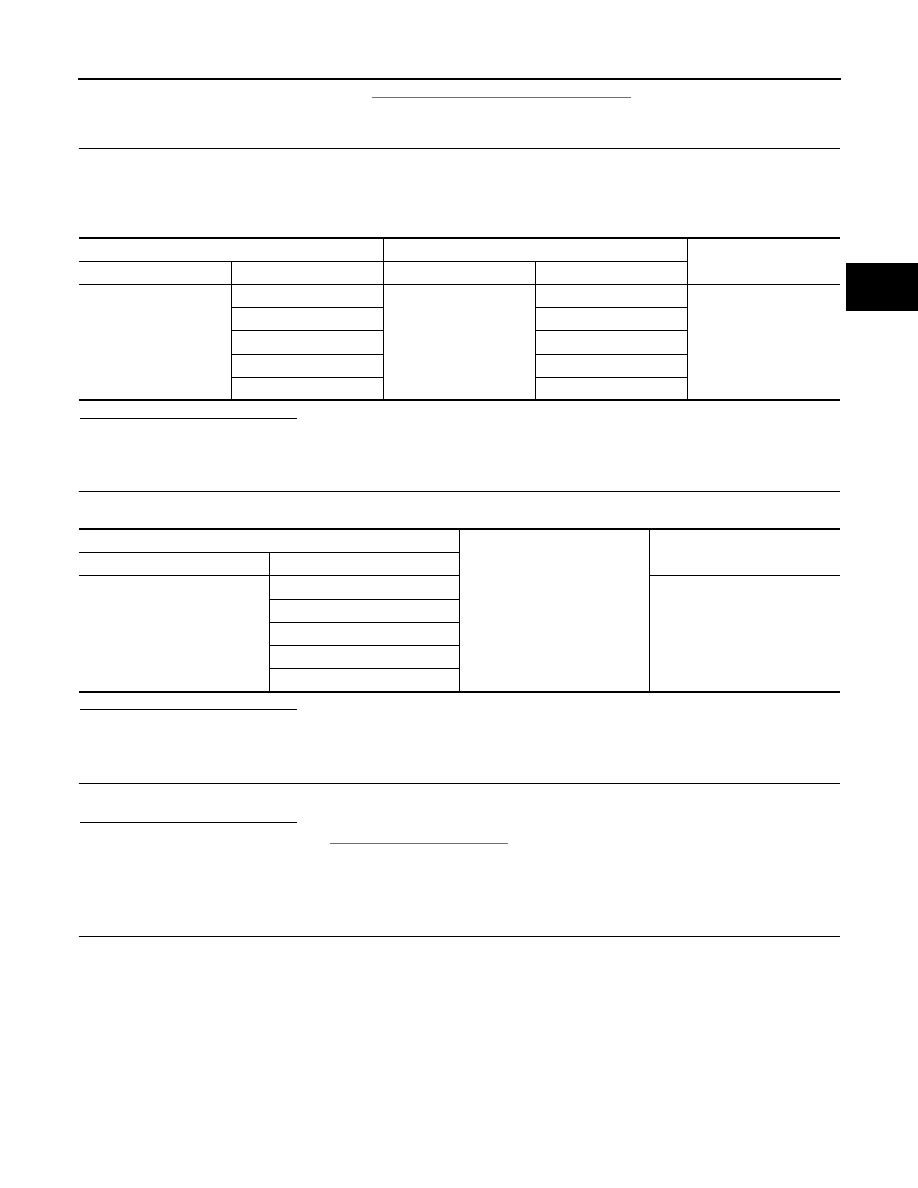
TCM vehicle side harness connector
CVT unit vehicle side harness connector
Continuity
Connector
Terminal
Connector
Terminal
F23
1
F24
5
Existed
2
14
3
15
4
18
11
4
TCM vehicle side harness connector
Ground
Continuity
Connector Terminal
F23
1
Not existed
2
3
4
11
TM-48
< DTC/CIRCUIT DIAGNOSIS >
[CVT: RE0F09B]
P0705 TRANSMISSION RANGE SWITCH A
Is the inspection result normal?
YES
>> INSPECTION END
NO
>> Replace transaxle assembly. Refer to
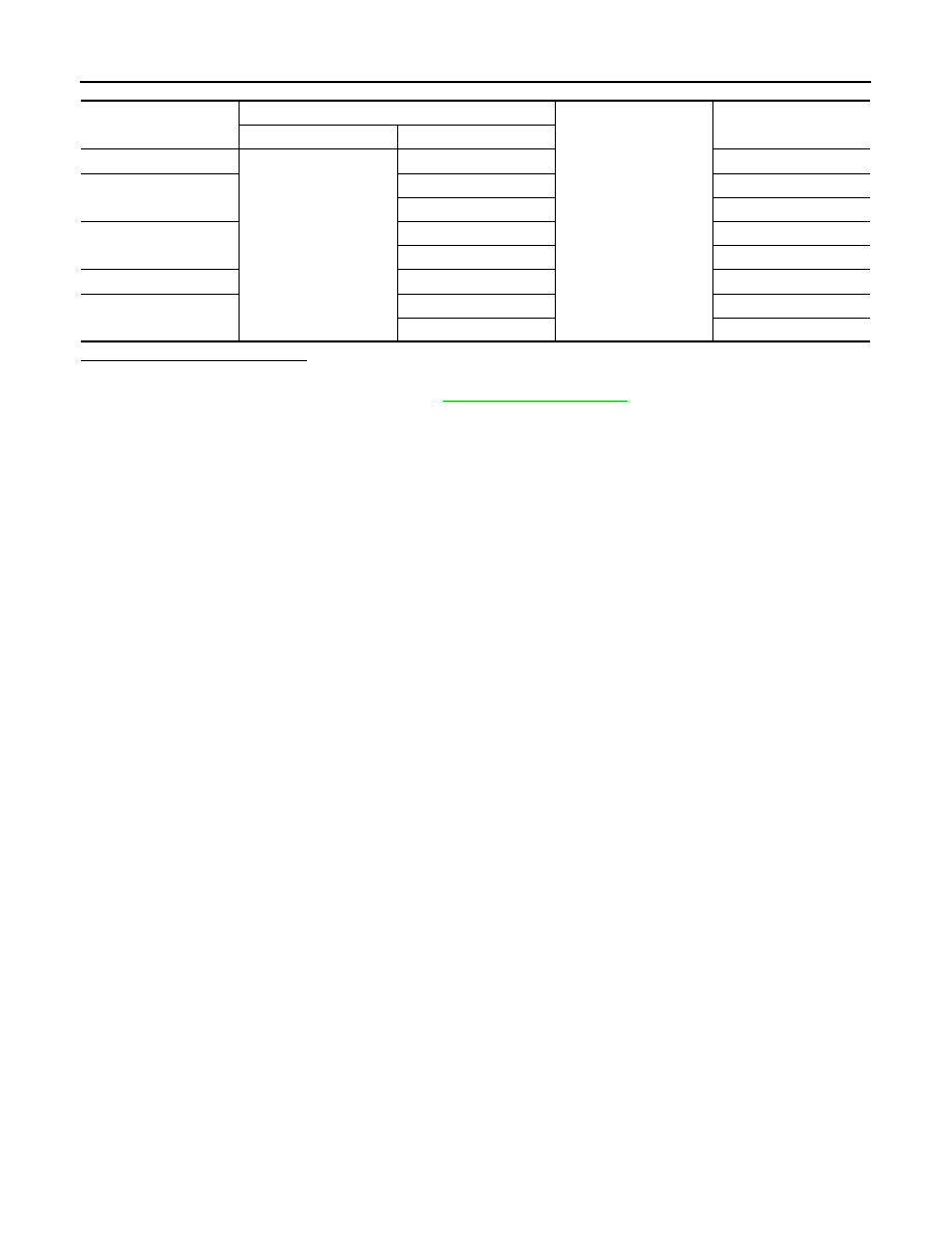
Shift position
CVT unit connector
Ground
Continuity
Connector
Terminal
P
F24
4, 5, 14, 15, 18
Not existed
R
4, 15
Existed
5, 14, 18
Not existed
N
4, 5
Existed
14, 15, 18
Not existed
D
4, 5, 14, 15, 18
Existed
L
5, 14, 18
Existed
4, 15
Not existed
P0710 TRANSMISSION FLUID TEMPERATURE SENSOR A
TM-49
< DTC/CIRCUIT DIAGNOSIS >
[CVT: RE0F09B]
C
E
F
G
H
I
J
K
L
M
A
B
TM
N
O
P
P0710 TRANSMISSION FLUID TEMPERATURE SENSOR A
Description
INFOID:0000000005513976
The CVT fluid temperature sensor detects the CVT fluid temperature and sends a signal to the TCM.
DTC Logic
INFOID:0000000005513977
DTC DETECTION LOGIC
DTC CONFIRMATION PROCEDURE
CAUTION:
Always drive vehicle at a safe speed.
NOTE:
Immediately after performing any “DTC CONFIRMATION PROCEDURE”, always turn ignition switch OFF.
Then wait at least 10 seconds before performing the next test.
1.
CHECK DTC DETECTION (PART 1)
With CONSULT-III
1.
Turn ignition switch ON.
2.
Select “DATA MONITOR”.
3.
Check that output voltage of CVT fluid temperature sensor is within the range specified below.
is the inspection result normal?
YES
>> Check intermittent incident. Refer to
GI-39, "Intermittent Incident"
.
NO-1 (“ATF TEMP SEN” indicates 0.15 or less.)>>Refer to
.
NO-2 (“ATF TEMP SEN” indicates 2.04 or more.)>>GO TO 2.
2.
CHECK DTC DETECTION (PART 2)
With CONSULT-III
1.
Turn ignition switch ON.
2.
Select “DATA MONITOR”.
3.
Start engine and maintain the following conditions for at least 14 minutes.
With GST
Follow the procedure “With CONSULT-III”.
Is “P0710” detected?
YES
>> Go to
NO
>> Check intermittent incident. Refer to
GI-39, "Intermittent Incident"
.
Diagnosis Procedure
INFOID:0000000005513978
1.
CHECK CVT FLUID TEMPERATURE SENSOR CIRCUIT
1.
Turn ignition switch OFF.
2.
Disconnect TCM connector.
3.
Check resistance between TCM vehicle side harness connector terminals.
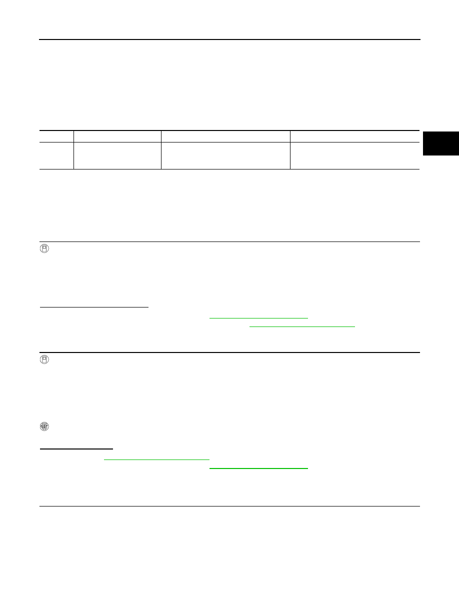
DTC
Trouble diagnosis name
DTC is detected if...
Possible cause
P0710
Transmission Fluid Tempera-
ture Sensor A Circuit
During running, the CVT fluid temperature
sensor signal voltage is excessively high or
low.
• Harness or connectors
(Sensor circuit is open or shorted.)
• CVT fluid temperature sensor
ATF TEMP SEN
: 0.16 – 2.03 V
RANGE
: “D” position
VEHICLE SPEED
: 10 km/h (6 MPH) or more
TM-50
< DTC/CIRCUIT DIAGNOSIS >
[CVT: RE0F09B]
P0710 TRANSMISSION FLUID TEMPERATURE SENSOR A
Is the inspection result normal?
YES
>> GO TO 5.
NO
>> GO TO 2.
2.
CHECK HARNESS BETWEEN TCM AND CVT UNIT (CVT TEMPERATURE SENSOR) (PART 1)
1.
Disconnect CVT unit connector.
2.
Check continuity between TCM vehicle side harness connector terminals and CVT unit vehicle side har-
ness connector terminals.
Is the inspection result normal?
YES
>> GO TO 3.
NO
>> Repair or replace damaged parts.
3.
CHECK HARNESS BETWEEN TCM AND CVT UNIT (CVT TEMPERATURE SENSOR) (PART 2)
Check continuity between TCM vehicle side harness connector terminals and ground.
Is the inspection result normal?
YES
>> GO TO 4.
NO
>> Repair or replace damaged parts.
4.
CHECK CVT FLUID TEMPERATURE SENSOR
Check CVT fluid temperature sensor. Refer to
TM-50, "Component Inspection (CVT Fluid Temperature Sen-
Is the inspection result normal?
YES
>> GO TO 5.
NO
>> Replace transaxle assembly. Refer to
5.
DETECT MALFUNCTIONING ITEMS
Check TCM connector pin terminals for damage or loose connection with harness connector.
Is the inspection result normal?
YES
NO
>> Repair or replace damaged parts.
Component Inspection (CVT Fluid Temperature Sensor)
INFOID:0000000005513979
1.
CHECK CVT FLUID TEMPERATURE SENSOR
Check resistance between CVT unit connector terminals.
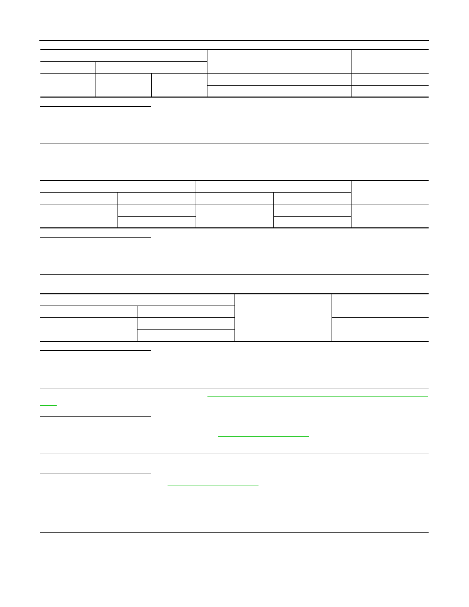
TCM vehicle side harness connector
Condition
Resistance (Approx.)
Connector
Terminal
F23
13
25
When CVT fluid temperature is 20
°
C (68
°
F)
6.5 k
Ω
When CVT fluid temperature is 80
°
C (176
°
F)
0.9 k
Ω
TCM vehicle side harness connector
CVT unit vehicle side harness connector
Continuity
Connector
Terminal
Connector
Terminal
F23
13
F24
17
Existed
25
19
TCM vehicle side harness connector
Ground
Continuity
Connector
Terminal
F23
13
Not existed
25
Нет комментариевНе стесняйтесь поделиться с нами вашим ценным мнением.
Текст