Nissan Murano Z51. Instruction — part 1422
DIAGNOSIS SYSTEM (TCM)
TM-39
< SYSTEM DESCRIPTION >
[CVT: RE0F09B]
C
E
F
G
H
I
J
K
L
M
A
B
TM
N
O
P
Diagnostic Tool Function
INFOID:0000000005513961
OBD-II SELF-DIAGNOSTIC PROCEDURE (WITH GST)
EC-124, "Diagnosis Tool Function"
.
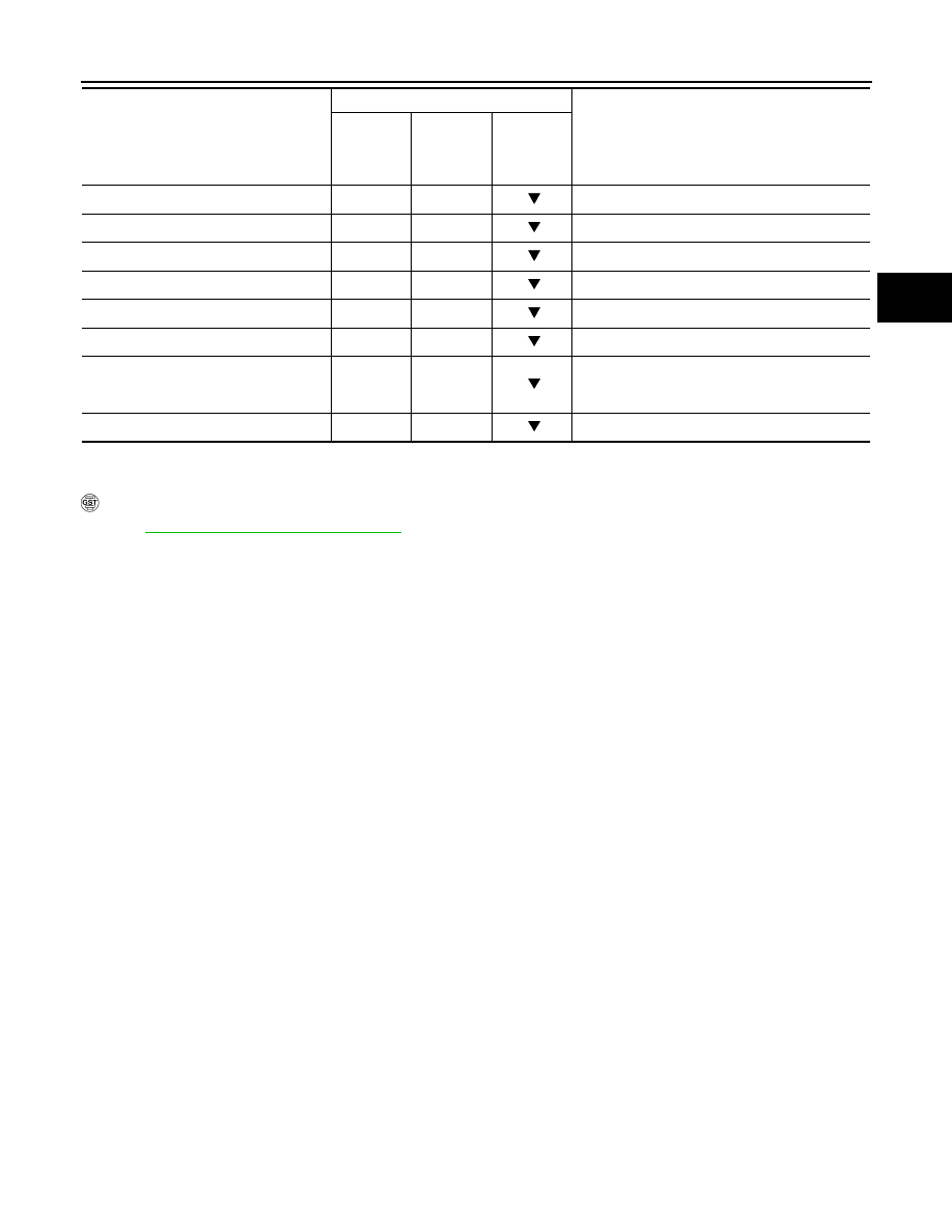
LUSEL SOL MON (On/Off)
—
—
—
STRTR RLY MON (On/Off)
—
—
Starter relay monitor
VDC ON (On/Off)
X
—
—
TCS ON (On/Off)
X
—
—
ABS ON (On/Off)
X
—
—
ACC ON (On/Off)
X
—
Not mounted but displayed.
RANGE
—
X
Indicates position is recognized by TCM. Indi-
cates a specific value required for control when
fail-safe function is activated.
M GEAR POS
—
X
Not mounted but displayed.
Monitored item (Unit)
Monitor item selection
Remarks
ECU IN-
PUT SIG-
NALS
MAIN SIG-
NALS
SELEC-
TION
FROM
MENU
TM-40
< DTC/CIRCUIT DIAGNOSIS >
[CVT: RE0F09B]
U1000 CAN COMM CIRCUIT
DTC/CIRCUIT DIAGNOSIS
U1000 CAN COMM CIRCUIT
Description
INFOID:0000000005513962
CAN (Controller Area Network) is a serial communication line for real time application. It is an on-vehicle mul-
tiplex communication line with high data communication speed and excellent malfunction detection ability.
Many electronic control units are equipped onto a vehicle, and each control unit shares information and links
with other control units during operation (not independent). In CAN communication, control units are con-
nected with 2 communication lines (CAN-H and CAN-L) allowing a high rate of information transmission with
less wiring. Each control unit transmits/receives data but selectively reads required data only.
DTC Logic
INFOID:0000000005513963
DTC DETECTION LOGIC
DTC CONFIRMATION PROCEDURE
NOTE:
Immediately after performing any “DTC CONFIRMATION PROCEDURE”, always turn ignition switch OFF.
Then wait at least 10 seconds before performing the next test.
1.
CHECK DTC DETECTION
With CONSULT-III
1.
Turn ignition switch ON.
2.
Start engine and wait for at least 6 seconds.
3.
Perform “Self Diagnostic Results” in “TRANSMISSION”.
With GST
Follow the procedure “With CONSULT-III”.
Is “U1000” detected?
YES
>> Go to
NO
>> Check intermittent incident. Refer to
GI-39, "Intermittent Incident"
.
Diagnosis Procedure
INFOID:0000000005513964
Go to
LAN-27, "CAN System Specification Chart"
.
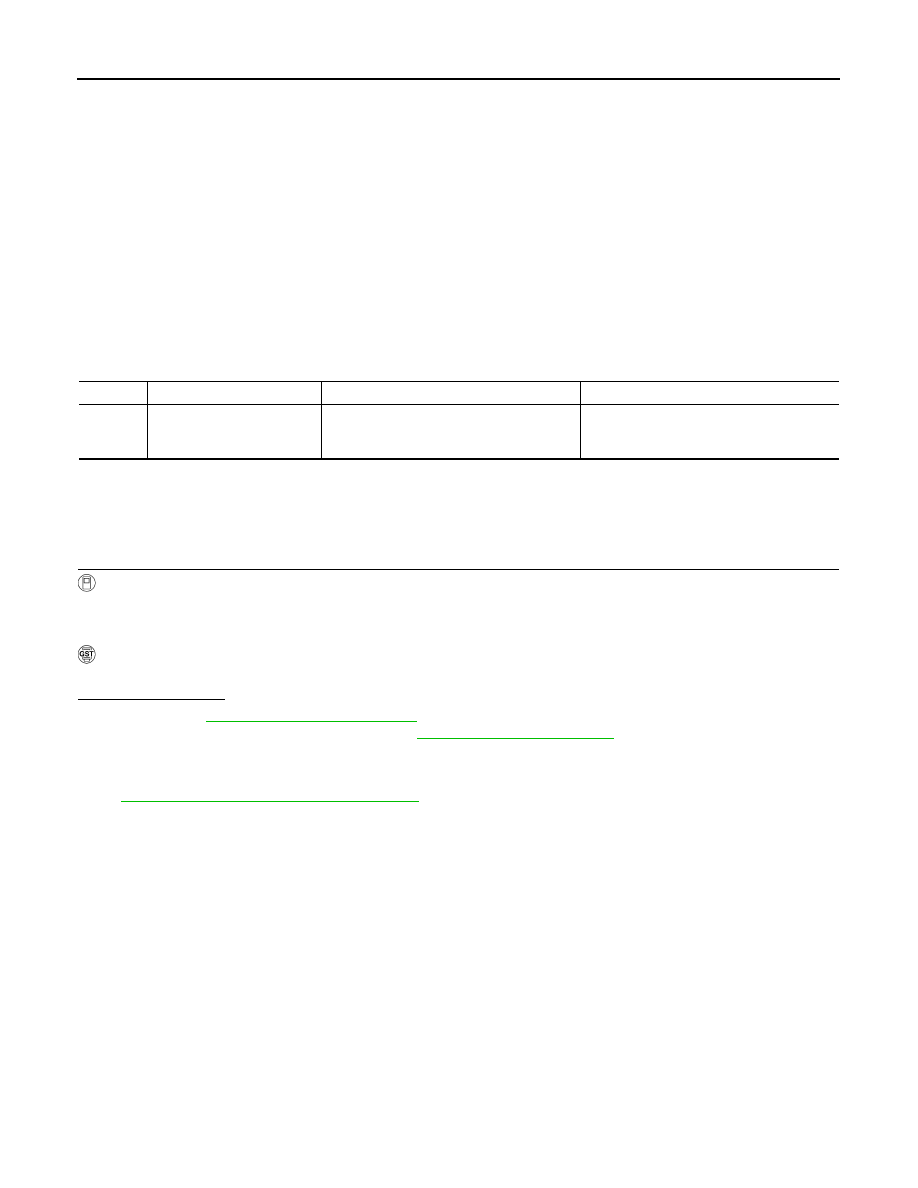
DTC
Trouble diagnosis name
DTC is detected if...
Possible cause
U1000
CAN Communication Line
When TCM is not transmitting or receiving
CAN communication signal for 2 seconds or
more.
Harness or connectors
(CAN communication line is open or short-
ed.)
P0615 STARTER RELAY
TM-41
< DTC/CIRCUIT DIAGNOSIS >
[CVT: RE0F09B]
C
E
F
G
H
I
J
K
L
M
A
B
TM
N
O
P
P0615 STARTER RELAY
Description
INFOID:0000000005513965
• TCM controls starter relay in IPDM E/R.
• TCM switches starter relay ON at “P” or “N” position and allows to cranking engine.
• Then it prohibits cranking other than at “P” or “N” position.
DTC Logic
INFOID:0000000005513966
DTC DETECTION LOGIC
DTC CONFIRMATION PROCEDURE
NOTE:
Immediately after performing any “DTC CONFIRMATION PROCEDURE”, always turn ignition switch OFF.
Then wait at least 10 seconds before performing the next test.
1.
CHECK DTC DETECTION
With CONSULT-III
1.
Turn ignition switch ON.
2.
Perform “Self Diagnostic Results” in “TRANSMISSION”.
Is “P0615” detected?
YES
>> Go to
NO
>> Check intermittent incident. Refer to
GI-39, "Intermittent Incident"
.
Diagnosis Procedure
INFOID:0000000005513967
1.
CHECK STARTER RELAY SIGNAL
1.
Turn ignition switch OFF.
2.
Disconnect IPDM E/R connector.
3.
Turn ignition switch ON.
4.
Check voltage between IPDM E/R vehicle side harness connector terminal and ground.
Is the inspection result normal?
YES
>> Check starter relay and starter control relay. Refer to
PCS-10, "Diagnosis Description"
.
NO
>> GO TO 2.
2.
CHECK HARNESS BETWEEN TCM AND IPDM E/R (PART 1)
1.
Turn ignition switch OFF.
2.
Disconnect TCM connector.
3.
Check continuity between TCM vehicle side harness connector terminal and IPDM E/R vehicle side har-
ness connector terminal.
Is the inspection result normal?
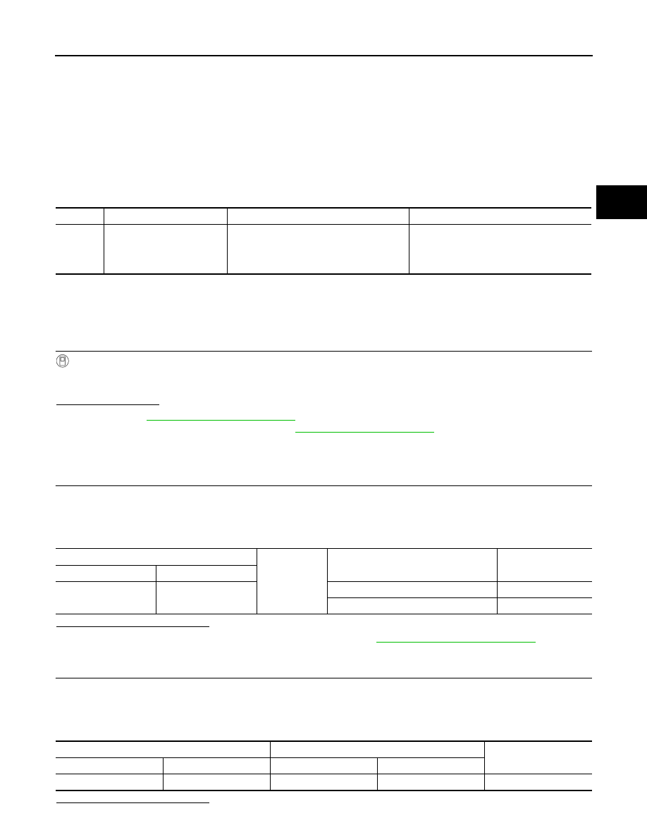
DTC
Trouble diagnosis name
DTC is detected if...
Possible cause
P0615
Starter Relay Circuit
If this signal is ON other than in “P” or “N” po-
sition, this is judged to be a malfunction.
(And if it is OFF in “P” or “N” position, this too
is judged to be a malfunction.)
• Harness or connectors
(Starter relay and TCM circuit is open or
shorted.)
• Starter relay circuit
IPDM E/R vehicle side harness connector
Ground
Condition
Voltage (Approx.)
Connector
Terminal
F12
72
Selector lever in “P” and “N” positions
Battery voltage
Selector lever in other positions
0 V
TCM vehicle side harness connector
IPDM E/R vehicle side harness connector
Continuity
Connector
Terminal
Connector
Terminal
F23
20
F12
72
Existed
TM-42
< DTC/CIRCUIT DIAGNOSIS >
[CVT: RE0F09B]
P0615 STARTER RELAY
YES
>> GO TO 3.
NO
>> Repair or replace damaged parts.
3.
CHECK HARNESS BETWEEN TCM AND IPDM E/R (PART 2)
Check continuity between TCM vehicle side harness connector terminal and ground.
Is the inspection result normal?
YES
>> GO TO 4.
NO
>> Repair or replace damaged parts.
4.
DETECT MALFUNCTIONING ITEMS
Check TCM connector pin terminals for damage or loose connection with harness connector.
Is the inspection result normal?
YES
NO
>> Repair or replace damaged parts.
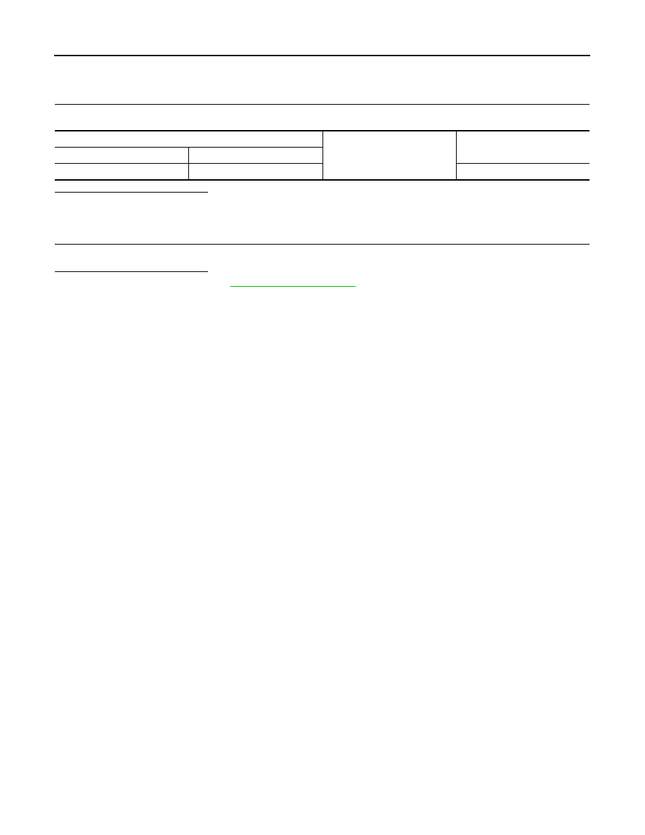
TCM vehicle side harness connector
Ground
Continuity
Connector
Terminal
F23
20
Not existed
Нет комментариевНе стесняйтесь поделиться с нами вашим ценным мнением.
Текст