Nissan Murano Z51. Instruction — part 573

EC-300
< DTC/CIRCUIT DIAGNOSIS >
[VQ35DE]
P0452 EVAP CONTROL SYSTEM PRESSURE SENSOR
YES
>> GO TO 12.
NO
>> GO TO 11.
11.
DETECT MALFUNCTIONING PART
Check the following.
• Harness connectors B4, E104
• Harness for open or short between EVAP control system pressure sensor and ECM
>> Repair open circuit, short to ground or short to power in harness or connectors.
12.
CHECK EVAP CONTROL SYSTEM PRESSURE SENSOR INPUT SIGNAL CIRCUIT FOR OPEN AND
SHORT
1.
Check the continuity between EVAP control system pressure sensor harness connector and ECM har-
ness connector.
2.
Also check harness for short to ground and short to power.
Is the inspection result normal?
YES
>> GO TO 14.
NO
>> GO TO 13.
13.
DETECT MALFUNCTIONING PART
Check the following.
• Harness connectors B4, E104
• Harness for open or short between EVAP control system pressure sensor and ECM
>> Repair open circuit, short to ground or short to power in harness or connectors.
14.
CHECK EVAP CONTROL SYSTEM PRESSURE SENSOR
EC-300, "Component Inspection"
Is the inspection result normal?
YES
>> GO TO 15.
NO
>> Replace EVAP control system pressure sensor.
15.
CHECK INTERMITTENT INCIDENT
GI-39, "Intermittent Incident"
>> INSPECTION END
Component Inspection
INFOID:0000000005536693
1.
CHECK EVAP CONTROL SYSTEM PRESSURE SENSOR
1.
Turn ignition switch OFF.
2.
Remove EVAP control system pressure sensor with its harness connector.
Always replace O-ring with a new one.
3.
Install a vacuum pump to EVAP control system pressure sensor.
4.
Turn ignition switch ON and check output voltage between ECM terminals under the following conditions.
EVAP control system pressure sensor
ECM
Continuity
Connector
Terminal
Connector
Terminal
B17
2
E16
86
Existed

P0452 EVAP CONTROL SYSTEM PRESSURE SENSOR
EC-301
< DTC/CIRCUIT DIAGNOSIS >
[VQ35DE]
C
D
E
F
G
H
I
J
K
L
M
A
EC
N
P
O
CAUTION:
• Always calibrate the vacuum pump gauge when using it.
• Never apply below -93.3 kPa (-0.952 kg/cm
2
, -13.53 psi) or pressure over 101.3 kPa (1.033 kg/cm
2
,
14.69 psi).
Is the inspection result normal?
YES
>> INSPECTION END
NO
>> Replace EVAP control system pressure sensor
ECM
Applied vacuum kPa
(kg/cm
2
, psi)
Voltage
Connector
+
–
Terminal
Terminal
E16
86
(EVAP control system
pressure sensor signal)
96
(Sensor ground)
Not applied
1.8 - 4.8 V
-26.7 (-0.272, -3.87)
2.1 to 2.5 V lower than
above value
EC-302
< DTC/CIRCUIT DIAGNOSIS >
[VQ35DE]
P0453 EVAP CONTROL SYSTEM PRESSURE SENSOR
P0453 EVAP CONTROL SYSTEM PRESSURE SENSOR
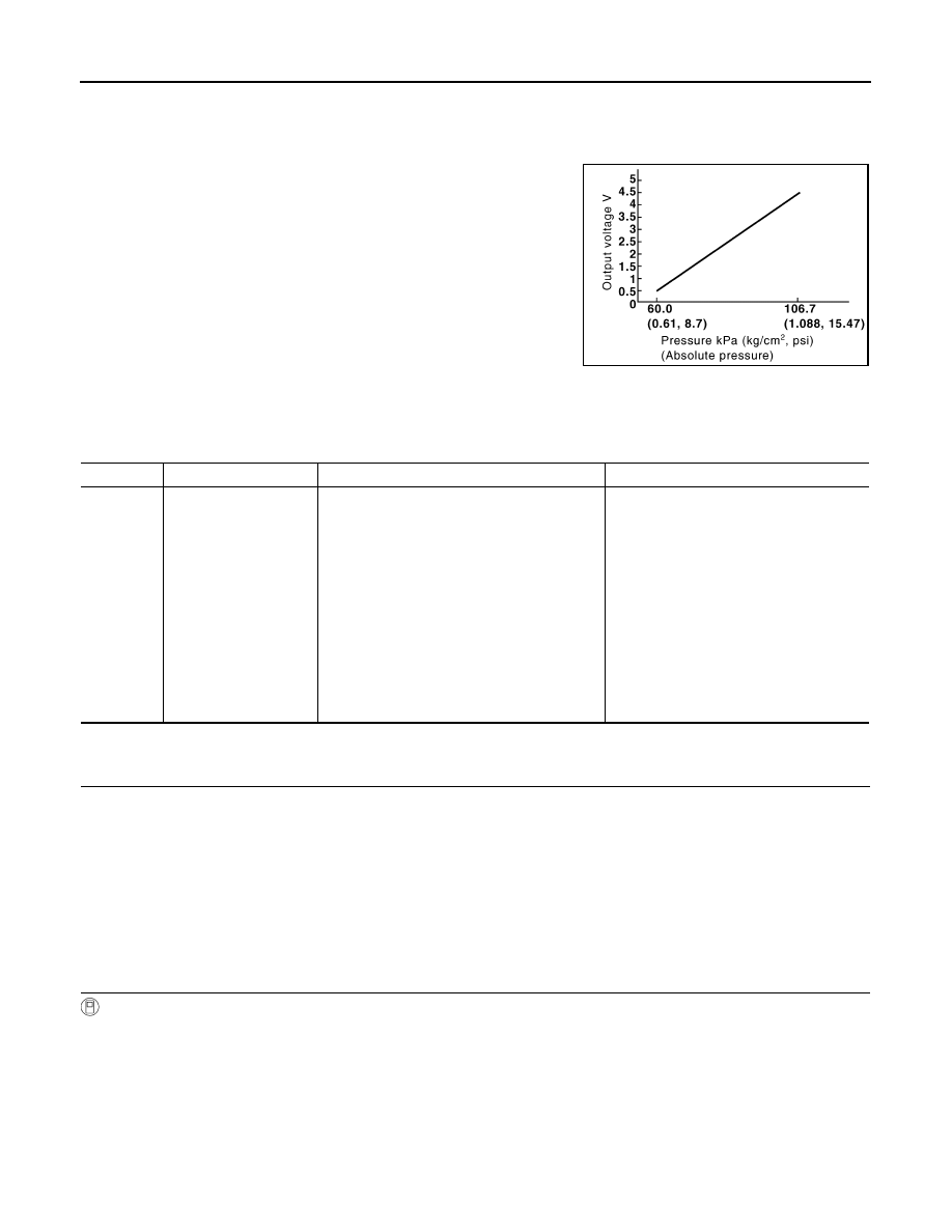
Description
INFOID:0000000005536694
The EVAP control system pressure sensor detects pressure in the
purge line. The sensor output voltage to the ECM increases as pres-
sure increases.
DTC Logic
INFOID:0000000005536695
DTC DETECTION LOGIC
DTC CONFIRMATION PROCEDURE
1.
PRECONDITIONING
If DTC Confirmation Procedure has been previously conducted, always perform the following before conduct-
ing the next test.
1.
Turn ignition switch OFF and wait at least 10 seconds.
2.
Turn ignition switch ON.
3.
Turn ignition switch OFF and wait at least 10 seconds.
TESTING CONDITION:
Always perform test at a temperature of 5
°
C (41
°
F) or more.
>> GO TO 2.
2.
PERFORM DTC CONFIRMATION PROCEDURE
With CONSULT-III
1.
Start engine and warm it up to normal operating temperature.
2.
Turn ignition switch OFF and wait at least 10 seconds.
3.
Turn ignition switch ON.
4.
Turn ignition switch OFF and wait at least 10 seconds.
5.
Turn ignition switch ON.
6.
Select “DATA MONITOR” mode with CONSULT-III.
7.
Check that “FUEL T/TMP SE” is more than 0
°
C (32
°
F).
8.
Start engine and wait at least 20 seconds.
9.
Check 1st trip DTC.
PBIB3370E
DTC No.
Trouble diagnosis name
DTC detecting condition
Possible cause
P0453
EVAP control system
pressure sensor high in-
put
An excessively high voltage from the sensor is
sent to ECM.
• Harness or connectors
(The sensor circuit is open or shorted.)
[CKP sensor (POS) circuit is shorted.]
(APP sensor 2 circuit is shorted.)
(Refrigerant pressure sensor circuit is
shorted.)
• EVAP control system pressure sensor
• Crankshaft position sensor (POS)
• Accelerator pedal position sensor
• Refrigerant pressure sensor
• EVAP canister vent control valve
• EVAP canister
• Rubber hose from EVAP canister vent
control valve to vehicle frame

P0453 EVAP CONTROL SYSTEM PRESSURE SENSOR
EC-303
< DTC/CIRCUIT DIAGNOSIS >
[VQ35DE]
C
D
E
F
G
H
I
J
K
L
M
A
EC
N
P
O
With GST
1.
Start engine and warm it up to normal operating temperature.
2.
Set voltmeter probes to ECM harness connector terminals.
3.
Check that the voltage is less than 4.2 V.
4.
Turn ignition switch OFF and wait at least 10 seconds.
5.
Turn ignition switch ON.
6.
Turn ignition switch OFF and wait at least 10 seconds.
7.
Start engine and wait at least 20 seconds.
8.
Check 1st trip DTC.
Is 1st trip DTC detected?
YES
>> Go to
NO
>> INSPECTION END
Diagnosis Procedure
INFOID:0000000005536696
1.
CHECK GROUND CONNECTION
1.
Turn ignition switch OFF.
2.
Check ground connection E38. Refer to Ground Inspection in
.
Is the inspection result normal?
YES
>> GO TO 2.
NO
>> Repair or replace ground connection.
2.
CHECK CONNECTOR
1.
Disconnect EVAP control system pressure sensor harness connector.
2.
Check that water is not inside connectors.
Is the inspection result normal?
YES
>> GO TO 3.
NO
>> Repair or replace harness connector.
3.
CHECK EVAP CONTROL SYSTEM PRESSURE SENSOR POWER SUPPLY CIRCUIT
1.
Turn ignition switch ON.
2.
Check the voltage between EVAP control system pressure sensor harness connector and ground.
Is the inspection result normal?
YES
>> GO TO 10.
NO
>> GO TO 4.
4.
CHECK EVAP CONTROL SYSTEM PRESSURE SENSOR POWER SUPPLY CIRCUIT-II
1.
Turn ignition switch OFF.
2.
Disconnect ECM harness connector.
3.
Check the continuity between EVAP control system pressure sensor harness connector and ECM har-
ness connector.
ECM
Connector
+
–
Terminal
Terminal
E16
95
(Fuel tank temperature sensor signal)
104
(Sensor ground)
EVAP control system pressure sensor
Ground
Voltage (V)
Connector
Terminal
B17
3
Ground
Approx. 5
Нет комментариевНе стесняйтесь поделиться с нами вашим ценным мнением.
Текст