Nissan Murano Z51. Instruction — part 456
DLK-332
< REMOVAL AND INSTALLATION >
[WITH INTELLIGENT KEY SYSTEM]
BACK DOOR
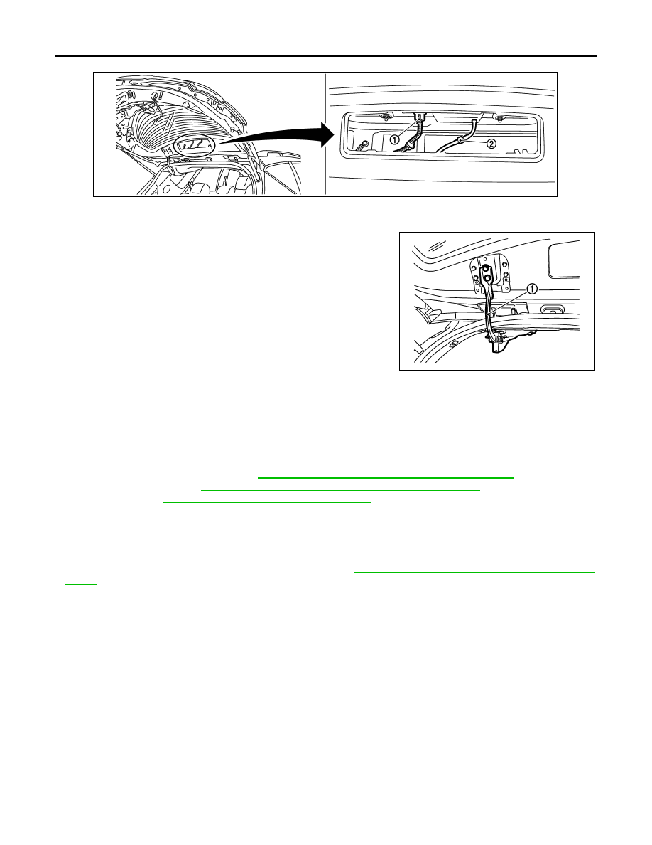
2.
Remove grommet, and then disconnect connector (1), and washer tube (2).
3.
Pull harness and washer tube out of back door.
4.
Support back door lock with the proper material to prevent it from falling.
5.
Remove mounting bolts of power back door drive assembly (1).
(back door side)
6.
Remove back door stay on back door side. Refer to
DLK-337, "BACK DOOR STAY : Removal and Instal-
.
7.
Remove back door hinge mounting bolts on back door and remove back door assembly.
8.
Remove the following parts after removing back door assembly.
• Bumper rubber
• Stud ball
• Back door lock assembly: Refer to
DLK-353, "DOOR LOCK : Removal and Installation"
.
• Touch sensor: Refer to
DLK-356, "TOUCH SENSOR : Removal and Installation"
• Patch: Refer to
DLK-353, "DOOR LOCK : Exploded View"
INSTALLATION
Install in the reverse order of removal.
CAUTION:
• Check back door open/close, lock/unlock operation after installation.
• After installation, perform fitting adjustment. Refer to
DLK-333, "BACK DOOR ASSEMBLY : Adjust-
JMKIA1917ZZ
JMKIA1918ZZ
BACK DOOR
DLK-333
< REMOVAL AND INSTALLATION >
[WITH INTELLIGENT KEY SYSTEM]
C
D
E
F
G
H
I
J
L
M
A
B
DLK
N
O
P
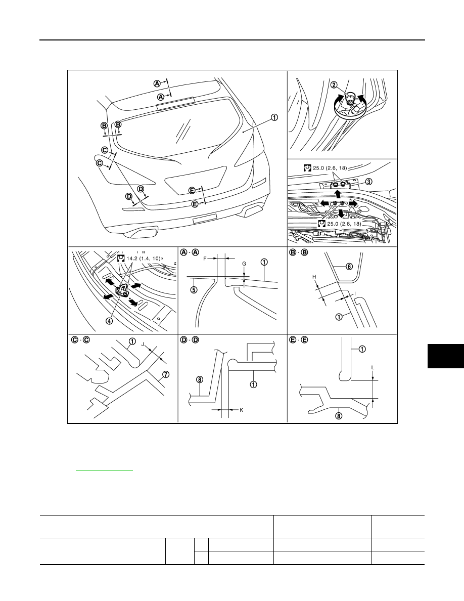
BACK DOOR ASSEMBLY : Adjustment
INFOID:0000000005517798
Check the clearance and the surface height between back door and each part by visually and touching.
If the clearance and the surface height are out of specification, adjust them according to the procedures
shown below.
Unit: mm (in)
1.
Back door assembly
2.
Bumper rubber
3.
Back door hinge
4.
Back door striker
5.
Roof panel
6.
Body side outer
7.
Rear combination lamp
8.
Rear bumper fascia
Refer to
JMKIA1835GB
Portion
Standard
Difference
(RH/LH)
Back door – Roof
A – A
F
Clearance
5.0 – 9.0 (0.197 – 0.354)
—
G
Surface height
-1.0 – 3.0 (-0.039 – 0.118)
—
DLK-334
< REMOVAL AND INSTALLATION >
[WITH INTELLIGENT KEY SYSTEM]
BACK DOOR
1.
Remove back door hinge cover. Refer to
INT-38, "Removal and Installation"
.
2.
Loosen back door hinge mounting bolts (back door side).
3.
Loosen bumper rubber.
4.
Remove luggage rear plate mask. Refer to
INT-35, "Removal and Installation"
5.
Loosen back door striker mounting bolts.
6.
Lift up back door approximately 100 – 150 mm (3.937 – 5.906 in) height then close it lightly and check that
it is engaged firmly with back door closed.
7.
Check the clearance and surface height.
8.
Finally tighten back door hinge, bumper rubber, and back door striker.
9.
Install back door hinge cover and luggage rear plate mask. Refer to
INT-38, "Removal and Installation"
and
INT-35, "Removal and Installation"
.
BACK DOOR STRIKER ADJUSTMENT
Adjust back door striker so that becomes parallel with back door lock insertion direction.
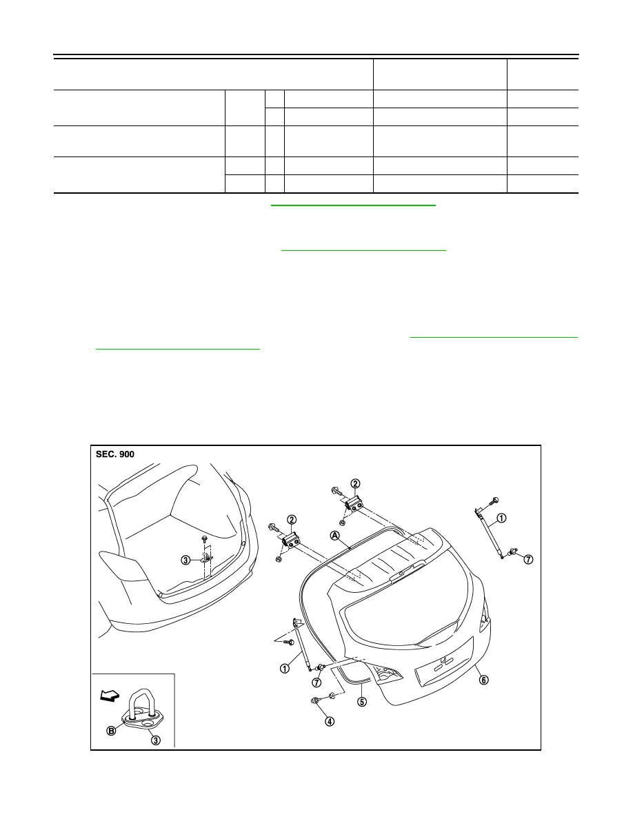
BACK DOOR STRIKER
BACK DOOR STRIKER : Exploded View
INFOID:0000000005517799
Back door – Rear fender
B – B
H
Clearance
4.0 – 8.0 (0.157 – 0.315)
—
I
Surface height
-2.0 – 2.0 (-0.079 – 0.079)
—
Back door – Rear combination
lamp
C – C
J
Clearance
4.0 – 8.0 (0.157 – 0.315)
< 2.0 (0.079)
Back door – Rear bumper fascia
D – D
K
Clearance
4.0 – 8.0 (0.157 – 0.315)
< 2.0 (0.079)
E – E
L
Clearance
5.0 – 9.0 (0.197 – 0.354)
—
Portion
Standard
Difference
(RH/LH)
1.
Back door stay
2.
Back door hinge
3.
Back door striker
4.
Bumper rubber
5.
Back door weather-strip
6.
Back door assembly
JMKIA3496ZZ
BACK DOOR
DLK-335
< REMOVAL AND INSTALLATION >
[WITH INTELLIGENT KEY SYSTEM]
C
D
E
F
G
H
I
J
L
M
A
B
DLK
N
O
P
BACK DOOR STRIKER : Removal and Installation
INFOID:0000000005517800
REMOVAL
1.
Remove luggage rear plate. Refer to
INT-35, "Removal and Installation"
2.
Remove mounting bolts, and then remove back door striker.
INSTALLATION
Install in the reverse order of removal.
CAUTION:
• Check back door open/close operation after installation.
• When removing and installing back door striker, be sure to perform the fitting adjustment. Refer to
DLK-333, "BACK DOOR ASSEMBLY : Adjustment"
.
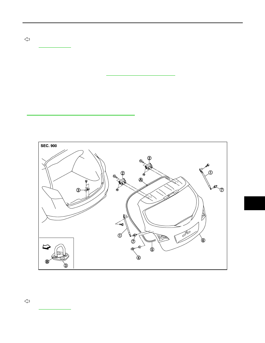
BACK DOOR HINGE
BACK DOOR HINGE : Exploded View
INFOID:0000000005517801
7.
Stud ball
A
: Center mark
B
: Front mark
: Vehicle front
Refer to
for symbols in the figure.
1.
Back door stay
2.
Back door hinge
3.
Back door striker
4.
Bumper rubber
5.
Back door weather-strip
6.
Back door assembly
7.
Stud ball
A
: Center mark
B
: Front mark
: Vehicle front
Refer to
for symbols in the figure.
JMKIA3496ZZ
Нет комментариевНе стесняйтесь поделиться с нами вашим ценным мнением.
Текст