Nissan Murano Z51. Instruction — part 1468
AIR MIX DOOR MOTOR
VTL-43
< REMOVAL AND INSTALLATION >
[WITHOUT 7 INCH DISPLAY]
C
D
E
F
G
H
J
K
L
M
A
B
VTL
N
O
P
AIR MIX DOOR MOTOR
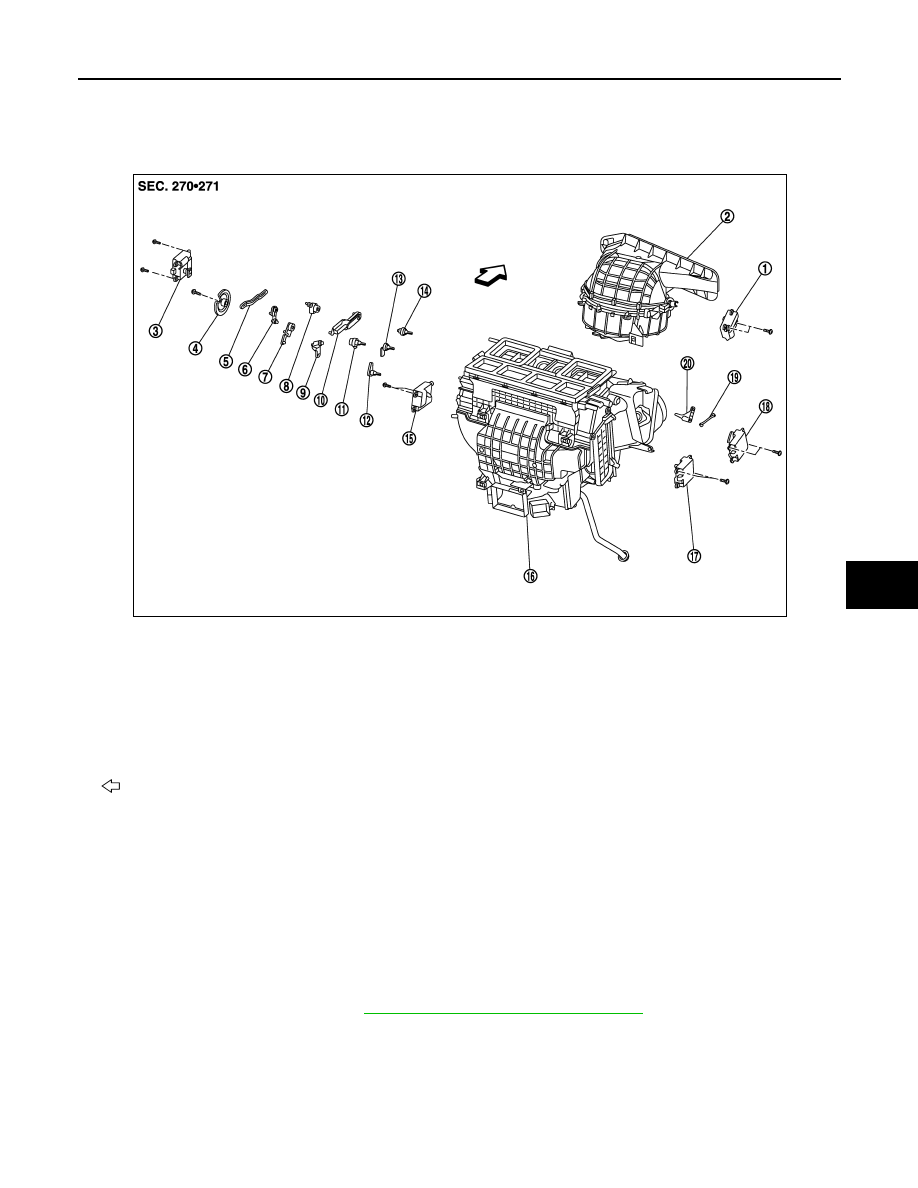
Exploded View
INFOID:0000000005517133
Removal and Installation
INFOID:0000000005517134
REMOVAL
Driver side
1.
Set the temperature (driver side) at 18
°
C (60
°
F).
CAUTION:
The angle may be out, when installing the air mix door motor to the air mix door, unless the above
procedure is performed.
2.
Disconnect the battery cable from the negative terminal.
3.
Remove the foot duct (left). Refer to
VTL-67, "FOOT DUCT : Exploded View"
.
1.
Intake door motor
2.
Bower unit assembly
3.
Mode door motor
4.
Main link
5.
Rod link
6.
Max. cool door link
7.
Max. cool door link
8.
Mode door lever
9.
Ventilator door link
10. Defroster door link
11.
Ventilator door lever
12. Foot door lever
13. Max. cool door lever
14.
Defroster door lever
15. Air mix door motor (driver side)
16. Heater & cooling unit assembly
17.
Air mix door motor (passenger side) 18. Upper ventilator door motor
19. Upper ventilator door rod
20.
Upper ventilator door lever
: Vehicle front
JPIIA1238ZZ
VTL-44
< REMOVAL AND INSTALLATION >
[WITHOUT 7 INCH DISPLAY]
AIR MIX DOOR MOTOR
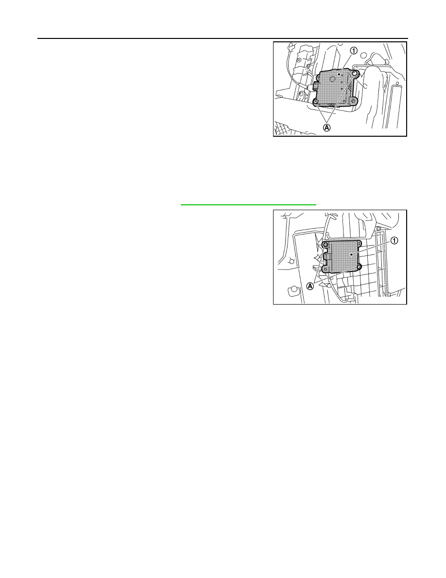
4.
Remove the mounting screws (A), and then remove the air mix
door motor (1).
5.
Disconnect the air mix door motor connector.
Passenger side
1.
Set the temperature (passenger side) at 18
°
C (60
°
F).
CAUTION:
The angle may be out, when installing the air mix door motor to the air mix door, unless the above
procedure is performed.
2.
Disconnect the battery cable from the negative terminal.
3.
Remove the foot duct (right). Refer to
VTL-67, "FOOT DUCT : Exploded View"
.
4.
Remove the mounting screws (A), and then remove the air mix
door motor (1).
5.
Disconnect the air mix door motor connector.
INSTALLATION
Install in the reverse order of removal.
JPIIA0577ZZ
JPIIA0578ZZ

HEATER CORE
VTL-45
< REMOVAL AND INSTALLATION >
[WITHOUT 7 INCH DISPLAY]
C
D
E
F
G
H
J
K
L
M
A
B
VTL
N
O
P
HEATER CORE
Exploded View
INFOID:0000000005517135
1.
Ventilator seal
2.
Upper ventilator seal
3.
Defroster seal
4.
Adapter case
5.
Center case
6.
Intake sensor bracket
7.
Intake sensor
8.
Upper ventilator door motor
9.
Upper ventilator door rod
10.
Upper ventilator door lever
11.
Filter cover
12. In-cabin microfilter/Air conditioner fil-
ter*
13.
Foot duct 1 (right)
14.
Foot duct 2 (right)
15. Air mix door motor (passenger side)
16.
Heater & cooling unit case cover
17.
Evaporator pipe assembly
18. O-ring
19.
Evaporator
20.
Expansion valve
21. Case packing
22.
Grommet
23.
Cooler pipe grommet
24. Drain hose
25.
Heater & cooling unit case (right)
26.
Air mix door (Slide door)
27. Heater pipe support
28.
Heater pipe grommet
29.
Heater & cooling unit case (left)
30. Heater core
31.
Heater pipe cover
32.
Foot duct 2 (left)
33. Foot duct 1 (left)
34.
Heater duct
35.
Aspirator
36. Aspirator hose
37.
Mode door motor
38.
Main link
39. Rod link
40.
Max. cool door link
41.
Ventilator door link
42. Foot door link
43.
Mode door lever
44.
Defroster door link
45. Ventilator door lever
JPIIA0454GB
VTL-46
< REMOVAL AND INSTALLATION >
[WITHOUT 7 INCH DISPLAY]
HEATER CORE
Removal and Installation
INFOID:0000000005517136
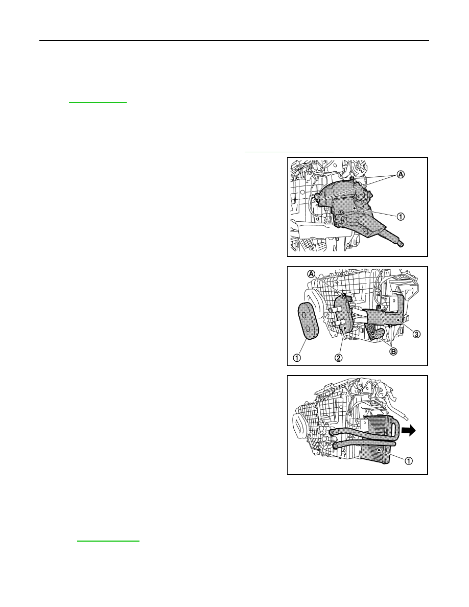
REMOVAL
1.
Remove the heater & cooling unit assembly. Refer to
.
2.
Remove the mounting screws (A), and then remove the foot
duct (left) (1).
3.
Remove the heater pipe grommet (1).
4.
Remove the mounting screw (A), and then remove the heater
pipe support (2).
5.
Remove the mounting screws (B), and then remove the heater
pipe cover (3).
6.
Slide the heater core (1) in the direction shown by the arrow, and
then remove it.
INSTALLATION
Install in the reverse order of removal.
CAUTION:
• Replace the O-ring with a new one. Apply a coat of compressor oil to the O-ring prior to installation.
• Check for refrigerant leakage when charging refrigerant.
NOTE:
• Refer to
when filling the radiator with engine coolant.
• Charge the refrigerant again.
46. Foot door lever
47.
Defroster door lever
48.
Max. cool door lever
49. Air mix door motor (driver side)
50.
Distributor upper case
51.
Distributor lower case
52. Ventilator door
53.
Foot door
54.
Max. cool door
55. Defroster door
56.
Upper ventilator door
*
: Models for Mexico.
for symbols in the figure.
JPIIA0579ZZ
JPIIA0580ZZ
JPIIA0581ZZ
Нет комментариевНе стесняйтесь поделиться с нами вашим ценным мнением.
Текст