Nissan Murano Z51. Instruction — part 1467
HEATER & COOLING UNIT ASSEMBLY
VTL-39
< REMOVAL AND INSTALLATION >
[WITHOUT 7 INCH DISPLAY]
C
D
E
F
G
H
J
K
L
M
A
B
VTL
N
O
P
7.
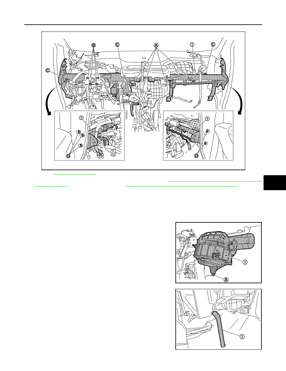
Remove the heater & cooling unit assembly and blower unit mounting bolts (A).
for symbols shown in the figure.
8.
Remove the steering column mounting nuts (B). Refer to
ST-18, "WITHOUT ELECTRIC MOTOR :
ST-21, "WITH ELECTRIC MOTOR : Exploded View"
(with elec-
tric motor).
9.
Remove the ground bolts (C) from the steering member (1).
10. Remove the harness clip from the steering member.
11. Disconnect the intake door motor and blower motor connectors.
12. Remove the steering member mounting bolts (D), and then remove the steering member.
13. Remove the mounting screw (A), and then remove the blower
unit (1).
14. Disconnect the drain hose (1) from heater & cooling unit assem-
bly.
JPIIA1241ZZ
JPIIA0567ZZ
JPIIA0572ZZ
VTL-40
< REMOVAL AND INSTALLATION >
[WITHOUT 7 INCH DISPLAY]
HEATER & COOLING UNIT ASSEMBLY
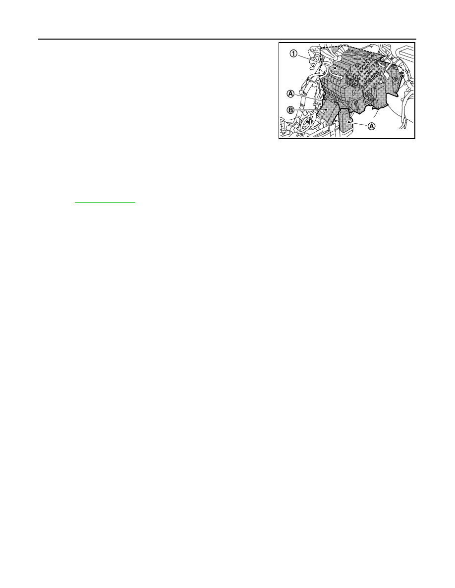
15. Remove the rear foot duct 1 (left/right) (A) and rear ventilator
duct 1 (B), and then remove the heater & cooling unit assembly
(1).
INSTALLATION
Install in the reverse order of removal.
CAUTION:
• Replace the O-ring with a new one. Apply a coat of compressor oil to the O-ring prior to installation.
• Check for refrigerant leakage when charging refrigerant.
NOTE:
• Refer to
when filling the radiator with engine coolant.
• Charge the refrigerant again.
JPIIA0573ZZ
UPPER VENTILATOR DOOR MOTOR
VTL-41
< REMOVAL AND INSTALLATION >
[WITHOUT 7 INCH DISPLAY]
C
D
E
F
G
H
J
K
L
M
A
B
VTL
N
O
P
UPPER VENTILATOR DOOR MOTOR
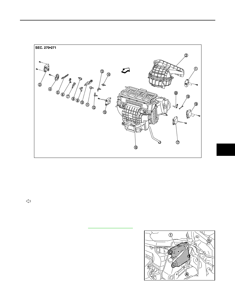
Exploded View
INFOID:0000000005517129
Removal and Installation
INFOID:0000000005517130
REMOVAL
1.
Remove the blower unit. Refer to
2.
Remove the mounting screws (A), and then remove the upper
ventilator door motor (1).
3.
Disconnect the upper ventilator door motor connector.
INSTALLATION
Install in the reverse order of removal.
1.
Intake door motor
2.
Bower unit assembly
3.
Mode door motor
4.
Main link
5.
Rod link
6.
Max. cool door link
7.
Max. cool door link
8.
Mode door lever
9.
Ventilator door link
10. Defroster door link
11.
Ventilator door lever
12. Foot door lever
13. Max. cool door lever
14.
Defroster door lever
15. Air mix door motor (driver side)
16. Heater & cooling unit assembly
17.
Air mix door motor (passenger side) 18. Upper ventilator door motor
19. Upper ventilator door rod
20.
Upper ventilator door lever
: Vehicle front
JPIIA1238ZZ
JPIIA0574ZZ
VTL-42
< REMOVAL AND INSTALLATION >
[WITHOUT 7 INCH DISPLAY]
MODE DOOR MOTOR
MODE DOOR MOTOR
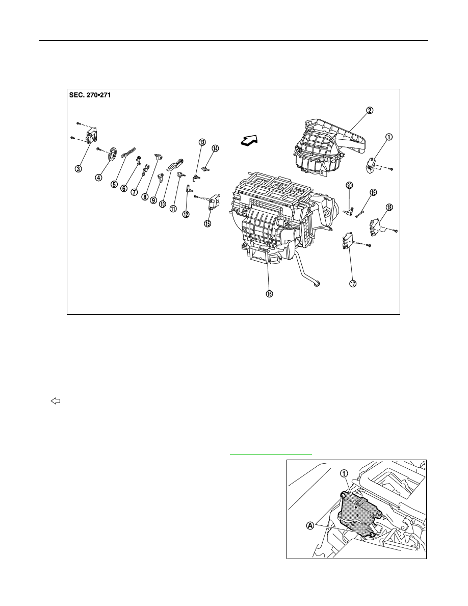
Exploded View
INFOID:0000000005517131
Removal and Installation
INFOID:0000000005517132
REMOVAL
1.
Remove the instrument panel assembly. Refer to
.
2.
Remove the mounting screws (A), and then remove the mode
door motor (1).
3.
Disconnect the mode door motor connector.
INSTALLATION
Install in the reverse order of removal.
1.
Intake door motor
2.
Bower unit assembly
3.
Mode door motor
4.
Main link
5.
Rod link
6.
Max. cool door link
7.
Max. cool door link
8.
Mode door lever
9.
Ventilator door link
10. Defroster door link
11.
Ventilator door lever
12. Foot door lever
13. Max. cool door lever
14.
Defroster door lever
15. Air mix door motor (driver side)
16. Heater & cooling unit assembly
17.
Air mix door motor (passenger side) 18. Upper ventilator door motor
19. Upper ventilator door rod
20.
Upper ventilator door lever
: Vehicle front
JPIIA1238ZZ
JPIIA0575ZZ
Нет комментариевНе стесняйтесь поделиться с нами вашим ценным мнением.
Текст