Nissan Murano Z51. Instruction — part 1263
B2108 STEERING LOCK RELAY
SEC-99
< DTC/CIRCUIT DIAGNOSIS >
[WITH INTELLIGENT KEY SYSTEM]
C
D
E
F
G
H
I
J
L
M
A
B
SEC
N
O
P
B2108 STEERING LOCK RELAY
Description
INFOID:0000000005515591
The steering lock relay ON signal is transmitted to IPDM E/R by BCM via CAN communication.
IPDM E/R turns the steering lock relay ON and transmits the release of the steering to BCM.
DTC Logic
INFOID:0000000005515592
DTC DETECTION LOGIC
NOTE:
If DTC B2108 is displayed with DTC U1000, first perform the trouble diagnosis for DTC U1000. Refer to
DTC CONFIRMATION PROCEDURE
1.
PERFORM DTC CONFIRMATION PROCEDURE
1.
Press the push-button ignition switch under the following conditions and wait for at least 1 second.
-
Selector lever is in the P or N position.
-
Do not depress brake pedal.
2.
Check “Self diagnostic result” with CONSULT-III.
Is DTC detected?
YES
>> Go to
NO
>> INSPECTION END
Diagnosis Procedure
INFOID:0000000005515593
1.
CHECK STEERING LOCK RELAY
Check voltage between IPDM E/R harness connector and ground.
Is the inspection normal?
YES
>> GO TO 2.
NO
>> Replace IPDM E/R. Refer to
PCS-35, "Removal and Installation"
.
2.
CHECK INTERMITTENT INCIDENT
GI-39, "Intermittent Incident"
.
>> INSPECTION END
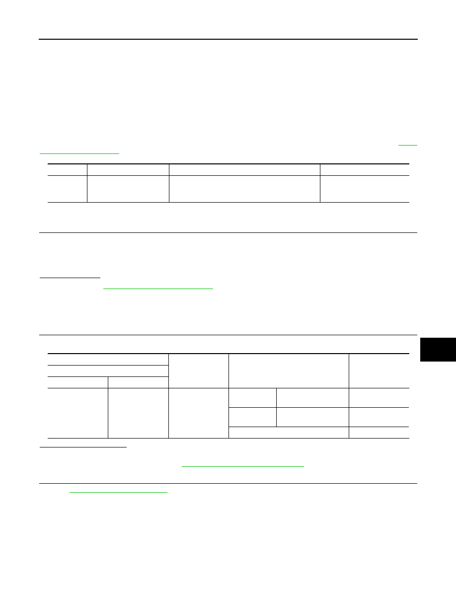
DTC No.
Trouble diagnosis name
DTC detecting condition
Possible cause
B2108
STRG LCK RELAY ON
IPDM E/R detects that the relay is stuck at ON posi-
tion for about 1 second even if the IPDM E/R re-
ceives steering lock relay ON/OFF signal from BCM.
IPDM E/R
(+)
(–)
Condition
Voltage (V)
(Approx.)
IPDM E/R
Connector
Terminal
E10
11
Ground
Ignition switch
OFF
A few seconds after
opening the driver door
Battery voltage
Ignition switch
LOCK
Press the push-button
ignition switch
Battery voltage
Ignition switch ACC or ON
0

SEC-100
< DTC/CIRCUIT DIAGNOSIS >
[WITH INTELLIGENT KEY SYSTEM]
B2109 STEERING LOCK RELAY
B2109 STEERING LOCK RELAY
Description
INFOID:0000000005515594
The steering lock relay ON signal is transmitted to IPDM E/R by BCM via CAN communication.
IPDM E/R turns the steering lock relay ON and transmits the release of the steering to BCM.
DTC Logic
INFOID:0000000005515595
DTC DETECTION LOGIC
NOTE:
• If DTC B2109 is displayed with DTC U1000, first perform the trouble diagnosis for DTC U1000. Refer to
.
• When IPDM E/R power supply voltage is low (Approx. 7 - 8 V for about 1 second), the DTC B2109 may be
detected.
DTC CONFIRMATION PROCEDURE
1.
PERFORM DTC CONFIRMATION PROCEDURE
1.
Press the push-button ignition switch under the following conditions and wait for at least 1 second.
-
Selector lever is in the P or N position.
-
Do not depress brake pedal.
2.
Check “Self diagnostic result” with CONSULT-III.
Is DTC detected?
YES
>> Go to
SEC-100, "Diagnosis Procedure"
.
NO
>> INSPECTION END
Diagnosis Procedure
INFOID:0000000005515596
1.
CHECK POWER SUPPLY CIRCUIT
Check IPDM E/R power supply circuit. Refer to
Is the circuit normal?
YES
>> GO TO 2.
NO
>> Repair or replace the malfunctioning part.
2.
CHECK FUSE
1.
Turn ignition switch OFF.
2.
Check 10A fuse (No. 48, located in IPDM E/R).
Is the inspection normal?
YES
>> Replace IPDM E/R. Refer to
PCS-35, "Removal and Installation"
NO
>>
Check the following.
• Harness for open or short between IPDM E/R and battery
• Fuse
DTC No.
Trouble diagnosis
name
DTC detecting condition
Possible cause
B2109
STRG LCK RELAY
OFF
IPDM E/R detects that the relay is stuck at OFF po-
sition for about 1 second even if the IPDM E/R re-
ceives steering lock relay ON/OFF signal from
BCM.
• Harness or connector (power sup-
ply circuit)
• IPDM E/R
• Battery

B210A STEERING LOCK UNIT
SEC-101
< DTC/CIRCUIT DIAGNOSIS >
[WITH INTELLIGENT KEY SYSTEM]
C
D
E
F
G
H
I
J
L
M
A
B
SEC
N
O
P
B210A STEERING LOCK UNIT
Description
INFOID:0000000005515597
There are 2 switches in the steering lock unit. IPDM E/R compares those 2 switches conditions to judge the
present steering status and transmit the result to BCM via CAN communication.
DTC Logic
INFOID:0000000005515598
DTC DETECTION LOGIC
NOTE:
If DTC B210A is displayed with DTC U1000, first perform the trouble diagnosis for DTC U1000. Refer to
DTC CONFIRMATION PROCEDURE
1.
PERFORM DTC CONFIRMATION PROCEDURE 1
1.
Press the push-button ignition switch under the following conditions and wait for at least 1 second.
-
Selector lever is in the P or N position.
-
Do not depress brake pedal.
2.
Check “Self diagnostic result” with CONSULT-III.
Is DTC detected?
YES
>> Go to
SEC-101, "Diagnosis Procedure"
.
NO
>> GO TO 2.
2.
PERFORM DTC CONFIRMATION PROCEDURE 2
1.
Turn ignition switch ON.
2.
Turn ignition switch OFF.
3.
Press driver side door switch and wait for at least 1 second.
4.
Check “Self diagnostic result” with CONSULT-III.
Is DTC detected?
YES
>> Go to
SEC-101, "Diagnosis Procedure"
.
NO
>> INSPECTION END
Diagnosis Procedure
INFOID:0000000005515599
1.
INSPECTION START
Perform inspection in accordance with procedure that confirms DTC.
Which procedure confirms DTC?
DTC confirmation procedure 1>>GO TO 2.
DTC confirmation procedure 2>>GO TO 6.
2.
CHECK BCM OUTPUT SIGNAL
1.
Turn ignition switch OFF.
2.
Disconnect steering lock unit connector and IPDM E/R connector.
3.
Check voltage between steering lock unit harness connector and ground.
DTC No.
Trouble diagnosis
name
DTC detecting condition
Possible cause
B210A
STRG LCK STATE
SW
IPDM E/R detects the mismatch between steering
condition switches 1 and 2 for 1 second
• Harness or connectors
[steering lock unit circuit (BCM
side) is open or shorted]
• Harness or connectors
[steering lock unit circuit (IPDM E/
R side) is open or shorted.]
• Steering lock unit
• IPDM E/R

SEC-102
< DTC/CIRCUIT DIAGNOSIS >
[WITH INTELLIGENT KEY SYSTEM]
B210A STEERING LOCK UNIT
Is the inspection result normal?
YES
>> GO TO 4.
NO
>> GO TO 3.
3.
CHECK STEERING LOCK UNIT CIRCUIT-1
1.
Disconnect BCM connector.
2.
Check continuity between steering lock unit harness connector and BCM harness connector.
3.
Check continuity between steering lock unit harness connector and ground.
Is the inspection result normal?
YES
>> GO TO 10.
NO
>> Repair or replace harness or connector.
4.
CHECK IPDM E/R OUTPUT SIGNAL
1.
Connect IPDM E/R connector.
2.
Disconnect BCM connector.
3.
Check voltage between steering lock unit harness connector and ground.
Is the inspection result normal?
YES
>> Replace steering lock unit.
NO
>> GO TO 5.
5.
CHECK STEERING LOCK UNIT CIRCUIT-2
1.
Disconnect IPDM E/R connector.
2.
Check continuity between steering lock unit harness connector and IPDM E/R harness connector.
3.
Check continuity between steering lock unit harness connector and ground.
Is the inspection result normal?
YES
>> GO TO 10.
(+)
(–)
Voltage (V)
(Approx.)
Steering lock unit
Connector
Terminal
M12
8
Ground
Battery voltage
Steering lock unit
BCM
Continuity
Connector
Terminal
Connector
Terminal
M12
8
M122
98
Existed
Steering lock unit
Ground
Continuity
Connector
Terminal
M12
8
Not existed
(+)
(–)
Voltage (V)
(Approx.)
Steering lock unit
Connector
Terminal
M12
8
Ground
Battery voltage
Steering lock unit
IPDM E/R
Continuity
Connector
Terminal
Connector
Terminal
M12
8
E10
33
Existed
Steering lock unit
Ground
Continuity
Connector
Terminal
M12
8
Not existed
Нет комментариевНе стесняйтесь поделиться с нами вашим ценным мнением.
Текст