Nissan Murano Z51. Instruction — part 216
AV
AUX IMAGE SIGNAL CIRCUIT
AV-643
< DTC/CIRCUIT DIAGNOSIS >
[BOSE AUDIO WITH NAVIGATION]
C
D
E
F
G
H
I
J
K
L
M
B
A
O
P
AUX IMAGE SIGNAL CIRCUIT
Description
INFOID:0000000005528778
Transmits the image signal of external device from auxiliary input jacks to front display unit.
Diagnosis Procedure
INFOID:0000000005528779
1.
CHECK CONTINUITY AUX IMAGE SIGNAL CIRCUIT
1.
Turn ignition switch OFF.
2.
Disconnect auxiliary input jacks connector and front display unit connector.
3.
Check continuity between auxiliary input jacks harness connector and front display unit harness connec-
tor.
4.
Check continuity between front display unit harness connector and ground.
Is the inspection result normal?
YES
>> GO TO 2.
NO
>> Repair harness or connector.
2.
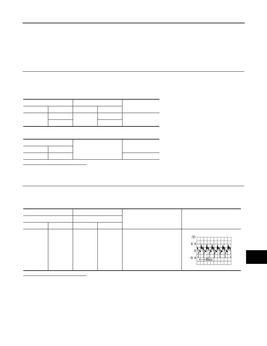
CHECK AUX IMAGE SIGNAL
1.
Connect auxiliary input jacks connector and front display unit connector.
2.
Turn ignition switch ON.
3.
Check signal between AV control unit harness connector using an oscilloscope.
Is the inspection result normal?
YES
>> Replace front display unit.
NO
>> Check that there is no malfunction in the external device.
Auxiliary input jacks
Front display unit
Continuity
Connector
Terminals
Connector
Terminals
M253
7
M49
15
Existed
8
5
Front display unit
Ground
Continuity
Connector
Terminal
M49
15
Not existed
(+)
(
−
)
Condition
Signal
Front display unit
Front display unit
Connector
Terminal
Connector
Terminal
M49
15
M49
5
When AUX image is displayed.
SKIB2251J

AV-644
< DTC/CIRCUIT DIAGNOSIS >
[BOSE AUDIO WITH NAVIGATION]
DISK EJECT SIGNAL CIRCUIT
DISK EJECT SIGNAL CIRCUIT
Description
INFOID:0000000005528780
The disk eject signal is output to AV control unit when the disk eject switch of preset switch is pressed.
Diagnosis Procedure
INFOID:0000000005528781
1.
CHECK CONTINUITY CD EJECT SIGNAL CIRCUIT
1.
Turn ignition switch OFF.
2.
Disconnect multifunction switch connector and AV control unit connector.
3.
Check continuity between multifunction switch harness connector and AV control unit harness connector.
4.
Check continuity between multifunction switch harness connector and ground.
Is the inspection result normal?
YES
>> GO TO 2.
NO
>> Repair harness or connector.
2.
CHECK AV CONTROL UNIT VOLTAGE
1.
Connect AV control unit connector.
2.
Turn ignition switch ON.
3.
Check voltage between AV control unit harness connector terminal 85 and ground.
Is the inspection result normal?
YES
>> Replace preset switch.
NO
>> Replace AV control unit.
Multifunction switch
AV control unit
Continuity
Connector
Terminal
Connector
Terminal
M125
14
M147
85
Existed
Multifunction switch
Ground
Continuity
Connector
Terminal
M125
14
Not existed
(+)
(
−
)
Voltage
(Approx.)
AV control unit
Connector
Terminal
M147
85
Ground
5.0 V
AV
MICROPHONE SIGNAL CIRCUIT
AV-645
< DTC/CIRCUIT DIAGNOSIS >
[BOSE AUDIO WITH NAVIGATION]
C
D
E
F
G
H
I
J
K
L
M
B
A
O
P
MICROPHONE SIGNAL CIRCUIT
Description
INFOID:0000000005528782
Supply power from AV control unit to microphone. The microphone transmits the sound/voice to the AV control
unit.
Diagnosis Procedure
INFOID:0000000005528783
1.
CHECK CONTINUITY BETWEEN AV CONTROL UNIT AND MICROPHONE CIRCUIT
1.
Turn ignition switch OFF.
2.
Disconnect AV control unit connector and microphone connector.
3.
Check continuity between AV control unit harness connector and microphone harness connector.
4.
Check continuity between AV control unit harness connector and ground.
Is the inspection result normal?
YES
>> GO TO 2.
NO
>> Repair harness or connector.
2.
CHECK VOLTAGE MICROPHONE VCC
1.
Connect AV control unit connector.
2.
Turn ignition switch ON.
3.
Check voltage between AV control unit harness connector.
Is the inspection result normal?
YES
>> GO TO 3.
NO
>> Replace AV control unit.
3.
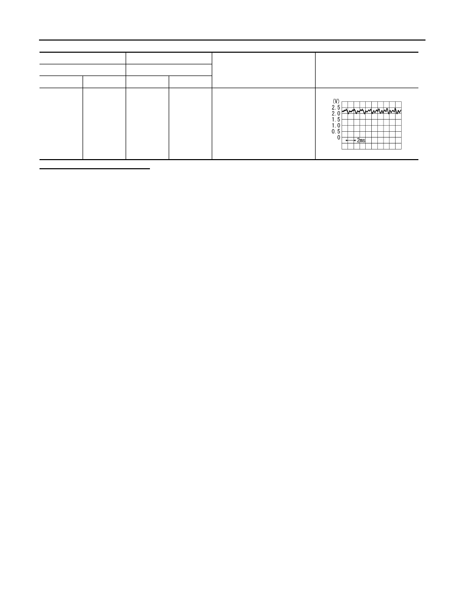
CHECK MICROPHONE SIGNAL
1.
Connect microphone connector.
2.
Check signal between AV control unit harness connector using an oscilloscope.
AV control unit
Microphone
Continuity
Connector
Terminals
Connector
Terminals
M145
26
R20
4
Existed
27
2
28
1
AV control unit
Ground
Continuity
Connector
Terminals
M145
26
Not existed
28
(+)
(
−
)
Voltage
(Approx.)
AV control unit
AV control unit
Connector
Terminal
Connector
Terminal
M145
26
M145
27
5.0 V
AV-646
< DTC/CIRCUIT DIAGNOSIS >
[BOSE AUDIO WITH NAVIGATION]
MICROPHONE SIGNAL CIRCUIT
Is the inspection result normal?
YES
>> Replace AV control unit.
NO
>> Replace microphone.
(+)
(
−
)
Condition
Signal
AV control unit
AV control unit
Connector
Terminal
Connector
Terminal
M145
28
M145
27
Give a voice
PKIB5037J
Нет комментариевНе стесняйтесь поделиться с нами вашим ценным мнением.
Текст