Nissan Murano Z51. Instruction — part 214
AV
POWER SUPPLY AND GROUND CIRCUIT
AV-635
< DTC/CIRCUIT DIAGNOSIS >
[BOSE AUDIO WITH NAVIGATION]
C
D
E
F
G
H
I
J
K
L
M
B
A
O
P
iPod ADAPTER : Diagnosis Procedure
INFOID:0000000005528763
1.
CHECK FUSE
Check for blown fuses.
Is the inspection result normal?
YES
>> GO TO 2.
NO
>> Be sure to eliminate the cause of malfunction before installing new fuse.
2.
CHECK POWER SUPPLY CIRCUIT
Check voltage between iPod adapter harness connector and ground.
Is the inspection result normal?
YES
>> INSPECTION END
NO
>> Check harness between iPod adapter and fuse.
Power source
Fuse No.
Battery
35
Ignition switch ACC or ON
19
Signal name
Connector No.
Terminal No.
Ignition switch position
Value (Approx.)
Battery power supply
M148
5
OFF
Battery voltage
ACC power supply
3
ACC

AV-636
< DTC/CIRCUIT DIAGNOSIS >
[BOSE AUDIO WITH NAVIGATION]
RGB (R: RED) SIGNAL CIRCUIT (AV CONTROL UNIT TO FRONT DISPLAY
UNIT)
RGB (R: RED) SIGNAL CIRCUIT (AV CONTROL UNIT TO FRONT DISPLAY
UNIT)
Description
INFOID:0000000005528764
Transmit the image displayed with AV control unit with RGB signal to the front display unit.
Diagnosis Procedure
INFOID:0000000005528765
1.
CHECK CONTINUITY RGB (R: RED) SIGNAL CIRCUIT
1.
Turn ignition switch OFF.
2.
Disconnect front display unit connector and AV control unit connector.
3.
Check continuity between front display unit harness connector and AV control unit harness connector.
4.
Check continuity between front display unit harness connector and ground.
Is the inspection result normal?
YES
>> GO TO 2.
NO
>> Repair harness or connector.
2.
CHECK RGB (R: RED) SIGNAL
1.
Connect front display unit connector and AV control unit connector.
2.
Turn ignition switch ON.
3.
Check signal between front display unit harness connector and ground using an oscilloscope.
Is the inspection result normal?
YES
>> Replace front display unit.
NO
>> Replace AV control unit.
Front display unit
AV control unit
Continuity
Connector
Terminal
Connector
Terminal
M49
17
M146
61
Existed
Front display unit
Ground
Continuity
Connector
Terminal
M49
17
Not existed
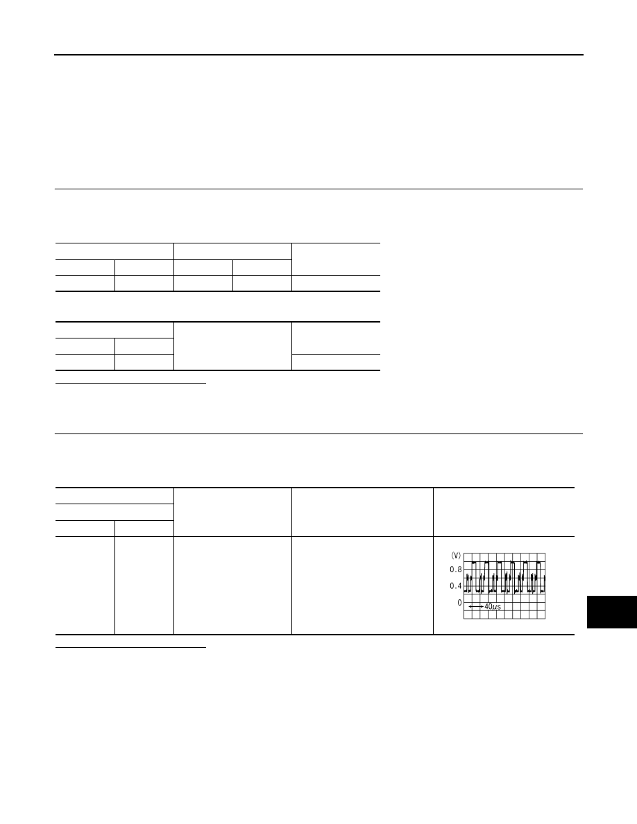
(+)
(
−
)
Condition
Signal
Front display unit
Connector
Terminal
M49
17
Ground
Start confirmation/adjustment
mode, and then display color bar
by selecting “Color Spectrum Bar”
on DISPLAY DIAGNOSIS screen.
JSNIA1029ZZ
AV
RGB (G: GREEN) SIGNAL CIRCUIT (AV CONTROL UNIT TO FRONT DISPLAY
UNIT)
AV-637
< DTC/CIRCUIT DIAGNOSIS >
[BOSE AUDIO WITH NAVIGATION]
C
D
E
F
G
H
I
J
K
L
M
B
A
O
P
RGB (G: GREEN) SIGNAL CIRCUIT (AV CONTROL UNIT TO FRONT DIS-
PLAY UNIT)
Description
INFOID:0000000005528766
Transmit the image displayed with AV control unit with RGB signal to the front display unit.
Diagnosis Procedure
INFOID:0000000005528767
1.
CHECK CONTINUITY RGB (G: GREEN) SIGNAL CIRCUIT
1.
Turn ignition switch OFF.
2.
Disconnect front display unit connector and AV control unit connector.
3.
Check continuity between front display unit harness connector and AV control unit harness connector.
4.
Check continuity between front display unit harness connector and ground.
Is the inspection result normal?
YES
>> GO TO 2.
NO
>> Repair harness or connector.
2.
CHECK RGB (G: GREEN) SIGNAL
1.
Connect front display unit connector and AV control unit connector.
2.
Turn ignition switch ON.
3.
Check signal between front display unit harness connector and ground using an oscilloscope.
Is the inspection result normal?
YES
>> Replace front display unit.
NO
>> Replace AV control unit.
Front display unit
AV control unit
Continuity
Connector
Terminal
Connector
Terminal
M49
6
M146
62
Existed
Front display unit
Ground
Continuity
Connector
Terminal
M49
6
Not existed
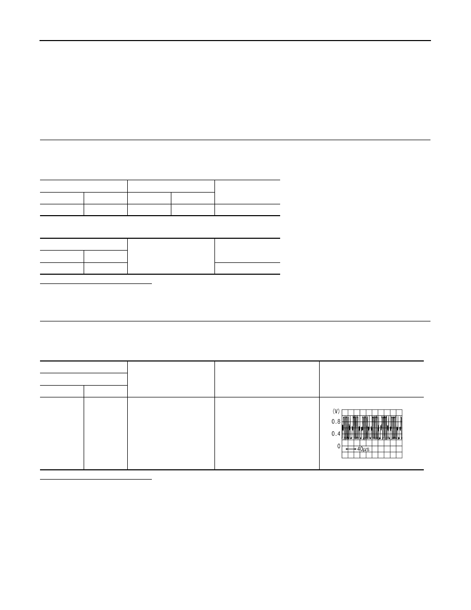
(+)
(
−
)
Condition
Signal
Front display unit
Connector
Terminal
M49
6
Ground
Start confirmation/adjustment
mode, and then display color bar
by selecting “Color Spectrum Bar”
on DISPLAY DIAGNOSIS screen.
JSNIA1030ZZ
AV-638
< DTC/CIRCUIT DIAGNOSIS >
[BOSE AUDIO WITH NAVIGATION]
RGB (B: BLUE) SIGNAL CIRCUIT (AV CONTROL UNIT TO FRONT DISPLAY
UNIT)
RGB (B: BLUE) SIGNAL CIRCUIT (AV CONTROL UNIT TO FRONT DIS-
PLAY UNIT)
Description
INFOID:0000000005528768
Transmit the image displayed with AV control unit with RGB signal to the front display unit.
Diagnosis Procedure
INFOID:0000000005528769
1.
CHECK CONTINUITY RGB (B: BLUE) SIGNAL CIRCUIT
1.
Turn ignition switch OFF.
2.
Disconnect front display unit connector and AV control unit connector.
3.
Check continuity between front display unit harness connector and AV control unit harness connector.
4.
Check continuity between front display unit harness connector and ground.
Is the inspection result normal?
YES
>> GO TO 2.
NO
>> Repair harness or connector.
2.
CHECK RGB (B: BLUE) SIGNAL
1.
Connect front display unit connector and AV control unit connector.
2.
Turn ignition switch ON.
3.
Check signal between front display unit harness connector and ground using an oscilloscope.
Is the inspection result normal?
YES
>> Replace front display unit.
NO
>> Replace AV control unit.
Front display unit
AV control unit
Continuity
Connector
Terminal
Connector
Terminal
M49
18
M146
63
Existed
Front display unit
Ground
Continuity
Connector
Terminal
M49
18
Not existed
(+)
(
−
)
Condition
Signal
Front display unit
Connector
Terminal
M49
18
Ground
Start confirmation/adjustment
mode, and then display color bar
by selecting “Color Spectrum Bar”
on DISPLAY DIAGNOSIS screen.
JSNIA1031ZZ
Нет комментариевНе стесняйтесь поделиться с нами вашим ценным мнением.
Текст