Nissan Murano Z51. Instruction — part 303

C1101, C1102, C1103, C1104 WHEEL SENSOR
BRC-35
< DTC/CIRCUIT DIAGNOSIS >
[VDC/TCS/ABS]
C
D
E
G
H
I
J
K
L
M
A
B
BRC
N
O
P
Is the inspection result normal?
YES
>> INSPECTION END
NO
>> Proceed to diagnosis procedure. Refer to
.
Special Repair Requirement
INFOID:0000000005517275
1.
ADJUSTMENT OF STEERING ANGLE SENSOR NEUTRAL POSITION AND CALIBRATION OF DECEL G
SENSOR
After removing/replacing an ABS actuator and electric unit (control unit), be sure to perform the following pro-
cedure.
• Adjustment of steering angle sensor neutral position: Refer to
BRC-9, "ADJUSTMENT OF STEERING
ANGLE SENSOR NEUTRAL POSITION : Description"
.
• Calibration of decel G sensor: Refer to
BRC-10, "CALIBRATION OF DECEL G SENSOR : Description"
.
>> END
Wheel sensor
Condition
Vehicle speed (DATA MONITOR)
FR LH SENSOR
Vehicle stopped
0 [km/h (MPH)]
Vehicle running (Note)
Nearly matches the speedometer dis-
play (
±
10% or less)
FR RH SENSOR
Vehicle stopped
0 [km/h (MPH)]
Vehicle running (Note)
Nearly matches the speedometer dis-
play (
±
10% or less)
RR LH SENSOR
Vehicle stopped
0 [km/h (MPH)]
Vehicle running (Note)
Nearly matches the speedometer dis-
play (
±
10% or less)
RR RH SENSOR
Vehicle stopped
0 [km/h (MPH)]
Vehicle running (Note)
Nearly matches the speedometer dis-
play (
±
10% or less)

BRC-36
< DTC/CIRCUIT DIAGNOSIS >
[VDC/TCS/ABS]
C1105, C1106, C1107, C1108 WHEEL SENSOR
C1105, C1106, C1107, C1108 WHEEL SENSOR
Description
INFOID:0000000005517276
When the sensor rotor rotates, the magnetic field changes. It converts the magnetic field changes to current
signals (rectangular wave) and transmits them to the ABS actuator and electric unit (control unit).
DTC Logic
INFOID:0000000005517277
DTC DETECTION LOGIC
DTC CONFIRMATION PROCEDURE
1.
DTC REPRODUCTION PROCEDURE
1.
Start the engine and drive the vehicle at 30 km/h (19 MPH) or more for approximately 1 minute.
2.
Perform self-diagnosis for “ABS” with CONSULT-III.
Is DTC “C1105”, “C1106”, “C1107” or “C1108” detected?
YES
>> Proceed to diagnosis procedure. Refer to
.
NO
>> INSPECTION END
Diagnosis Procedure
INFOID:0000000005517278
CAUTION:
Never check between wheel sensor harness connector terminals.
1.
CHECK TIRE
Check air pressure, wear, and size. Refer to
.
Is the inspection result normal?
YES
>> GO TO 2.
NO
>> Repair or replace error-detected parts.
2.
CHECK WHEEL SENSOR AND SENSOR ROTOR
• Check wheel sensor for damage, disconnection or looseness.
• Check sensor rotor for damage.
Is the inspection result normal?
YES
>> GO TO 3.
NO
>>
Repair wheel sensor mount or replace wheel sensor or replace sensor rotor.
• Front wheel sensor: Refer to
BRC-110, "FRONT WHEEL SENSOR : Exploded View"
.
• Rear wheel sensor: Refer to
BRC-111, "REAR WHEEL SENSOR : Exploded View"
.
• Front sensor rotor: Refer to
BRC-112, "FRONT SENSOR ROTOR : Exploded View"
.
• Rear sensor rotor: Refer to
BRC-112, "REAR SENSOR ROTOR : Exploded View"
.
3.
CHECK CONNECTOR
1.
Turn the ignition switch OFF.
2.
Disconnect ABS actuator and electric unit (control unit) connector.
3.
Disconnect malfunctioning wheel sensor connector.
4.
Check terminal to see if it is deformed, disconnected, loose, etc.
Is the inspection result normal?
DTC
Display item
Malfunction detected condition
Possible cause
C1105
RR RH SENSOR-2
Signal from rear RH wheel sensor does not match other
3 wheel speed signal.
• Harness or connector
• Wheel sensor
• Sensor rotor
• ABS actuator and electric unit
(control unit)
• Sensor rotor
C1106
RR LH SENSOR-2
Signal from rear LH wheel sensor does not match other
3 wheel speed signal.
C1107
FR RH SENSOR-2
Signal from front RH wheel sensor does not match other
3 wheel speed signal.
C1108
FR LH SENSOR-2
Signal from front LH wheel sensor does not match other
3 wheel speed signal.
C1105, C1106, C1107, C1108 WHEEL SENSOR
BRC-37
< DTC/CIRCUIT DIAGNOSIS >
[VDC/TCS/ABS]
C
D
E
G
H
I
J
K
L
M
A
B
BRC
N
O
P
YES
>> GO TO 4.
NO
>> Repair or replace error-detected parts.
4.
CHECK WHEEL SENSOR HARNESS
1.
Check the continuity between ABS actuator and electric unit (control unit) harness connector and wheel
sensor harness connector. (Also check continuity when steering wheel is turned right and left and when
sensor harness inside the wheel house is moved.)
Measurement terminal for signal circuit
Measurement terminal for power supply circuit
2.
Check the continuity between ABS actuator and electric unit (control unit) harness connector.
Is the inspection result normal?
YES
>> GO TO 5.
NO
>> Repair or replace error-detected parts.
5.
REPLACE WHEEL SENSOR
1.
Replace wheel sensor.
2.
Erase self-diagnosis results for “ABS” with CONSULT-III.
3.
Start the engine and drive the vehicle at 30 km/h (19 MPH) or more for approximately 1 minute.
4.
Perform self-diagnosis for “ABS” with CONSULT-III.
Is DTC “C1105”, “C1106”, “C1107” or “C1108” detected?
YES
>> Replace ABS actuator and electric unit (control unit). Refer to
.
NO
>> INSPECTION END
Component Inspection
INFOID:0000000005517279
1.
CHECK DATA MONITOR
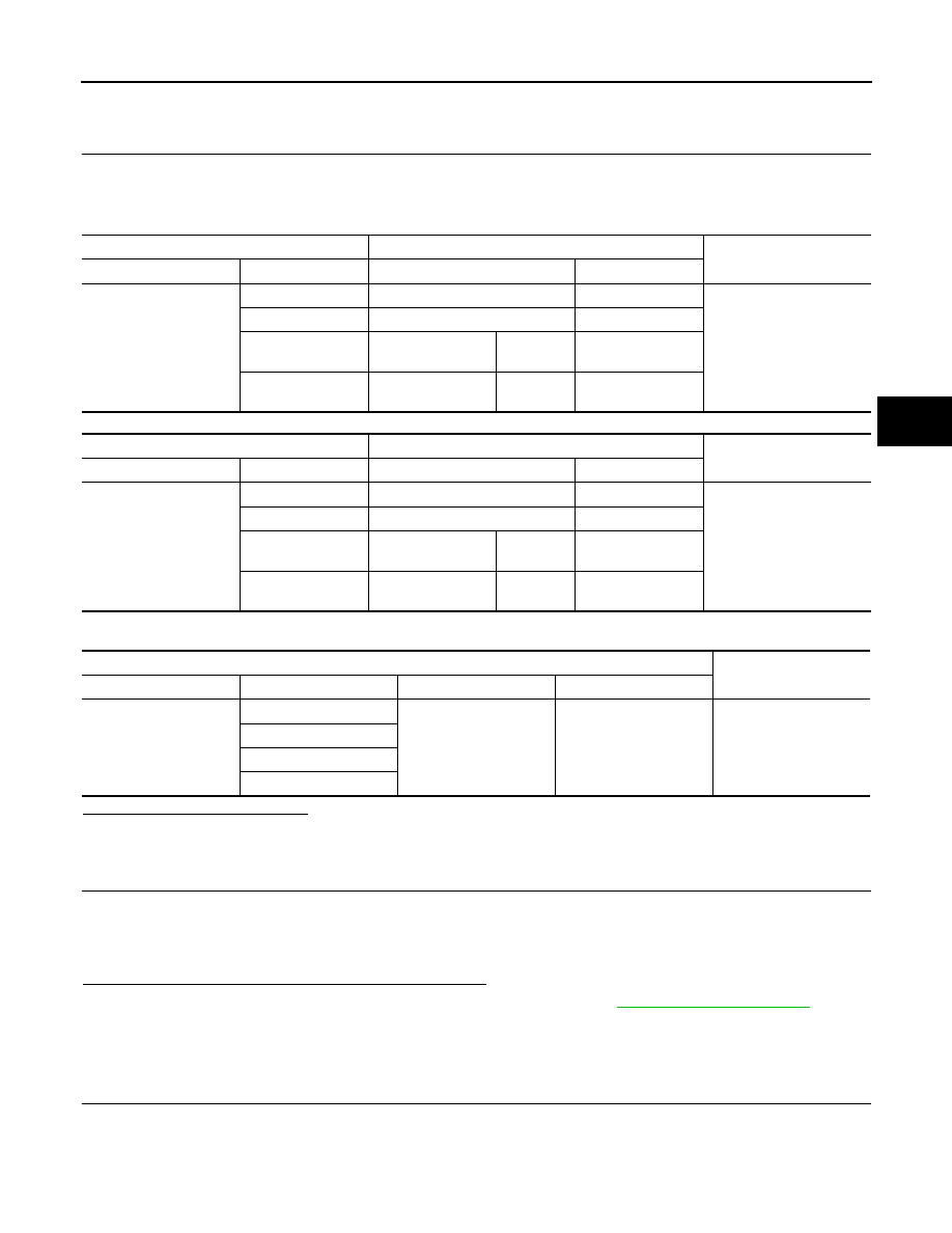
Select “ABS”, “DATA MONITOR” in order with CONSULT-III, select “FR LH SENSOR”, “FR RH SENSOR”,
“RR LH SENSOR”, and “RR RH SENSOR”, and check the vehicle speed.
ABS actuator and electric unit (control unit)
Wheel sensor
Continuity
Connector
Terminal
Connector
Terminal
E36
6
E39 (Front RH)
4
Existed
8
E22 (Front LH)
2
12
C4 (2WD models)
C6 (AWD models)
(Rear RH)
8
2
C3 (2WD models)
C5 (AWD models)
(Rear LH)
6
ABS actuator and electric unit (control unit)
Wheel sensor
Continuity
Connector
Terminal
Connector
Terminal
E36
5
E39 (Front RH)
3
Existed
9
E22 (Front LH)
1
11
C4 (2WD models)
C6 (AWD models)
(Rear RH)
7
3
C3 (2WD models)
C5 (AWD models)
(Rear LH)
5
ABS actuator and electric unit (control unit)
Continuity
Connector
Terminal
Connector
Terminal
E36
6, 5
E36
13, 26
Not existed
8, 9
12, 11
2, 3

BRC-38
< DTC/CIRCUIT DIAGNOSIS >
[VDC/TCS/ABS]
C1105, C1106, C1107, C1108 WHEEL SENSOR
Is the inspection result normal?
YES
>> INSPECTION END
NO
>> Proceed to diagnosis procedure. Refer to
.
Special Repair Requirement
INFOID:0000000005532210
1.
ADJUSTMENT OF STEERING ANGLE SENSOR NEUTRAL POSITION AND CALIBRATION OF DECEL G
SENSOR
After removing/replacing an ABS actuator and electric unit (control unit), be sure to perform the following pro-
cedure.
• Adjustment of steering angle sensor neutral position: Refer to
BRC-9, "ADJUSTMENT OF STEERING
ANGLE SENSOR NEUTRAL POSITION : Description"
.
• Calibration of decel G sensor: Refer to
BRC-10, "CALIBRATION OF DECEL G SENSOR : Description"
.
>> END
Wheel sensor
Condition
Vehicle speed (DATA MONITOR)
FR LH SENSOR
Vehicle stopped
0 [km/h (MPH)]
Vehicle running (Note)
Nearly matches the speedometer dis-
play (
±
10% or less)
FR RH SENSOR
Vehicle stopped
0 [km/h (MPH)]
Vehicle running (Note)
Nearly matches the speedometer dis-
play (
±
10% or less)
RR LH SENSOR
Vehicle stopped
0 [km/h (MPH)]
Vehicle running (Note)
Nearly matches the speedometer dis-
play (
±
10% or less)
RR RH SENSOR
Vehicle stopped
0 [km/h (MPH)]
Vehicle running (Note)
Nearly matches the speedometer dis-
play (
±
10% or less)
Нет комментариевНе стесняйтесь поделиться с нами вашим ценным мнением.
Текст