Nissan Murano Z51. Instruction — part 340
CHG
L TERMINAL CIRCUIT (OPEN)
CHG-11
< DTC/CIRCUIT DIAGNOSIS >
C
D
E
F
G
H
I
J
K
L
B
A
O
P
N
L TERMINAL CIRCUIT (OPEN)
Description
INFOID:0000000005514986
The “L” terminal circuit controls the charge warning lamp. The charge warning lamp illuminates when the igni-
tion switch is set to ON or START. When the alternator is providing sufficient voltage with the engine running,
the charge warning lamp will go off. If the charge warning lamp illuminates with the engine running, a malfunc-
tion is indicated.
Diagnosis Procedure
INFOID:0000000005514987
1.
CHECK “L” TERMINAL CONNECTION
1.
Turn ignition switch OFF.
2.
Check if “L” terminal is clean and tight.
Is the inspection result normal?
YES
>> GO TO 2.
NO
>> Repair “L” terminal connection. Confirm repair by performing complete Starting/Charging system
test. Refer to Technical Service Bulletin.
2.
CHECK “L” TERMINAL CIRCUIT (OPEN)
1.
Disconnect alternator connector.
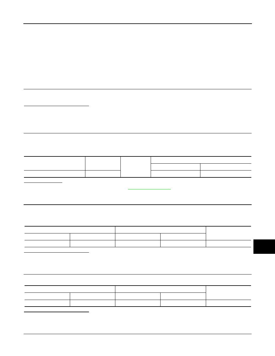
2.
Apply ground to alternator harness connector terminal.
3.
Check condition of the charge warning lamp with the ignition switch in the ON position.
Does it illuminate?
YES
>> “L” terminal circuit is normal. Refer to
NO
>> GO TO 3.
3.
CHECK HARNESS CONTINUITY (OPEN CIRCUIT)
1.
Disconnect the battery cable from the negative terminal.
2.
Disconnect the combination meter connector.
3.
Check continuity between alternator harness connector and combination meter harness connector.
Is the inspection result normal?
YES
>> GO TO 4.
NO
>> Repair the harness or connector.
4.
CHECK HARNESS CONTINUITY (OPEN CIRCUIT)
Check continuity between combination meter harness connector and fuse block.
Is the inspection result normal?
YES
>> GO TO 5.
NO
>> Repair the harness.
5.
CHECK POWER SUPPLY CIRCUIT
1.
Connect the battery cable to the negative terminal.
Alternator harness connector
Terminal
Ground
Condition
Ignition switch position
Charge warning lamp
F60
3
ON
illuminate
Alternator harness connector
Combination meter harness connector
Continuity
Connector No.
Terminal No.
Connector No.
Terminal No.
F60
3
M34
25
Existed
Combination meter harness connector
Fuse block
Continuity
Connector No.
Terminal No.
Connector No.
Terminal No.
M34
2
M3
12C
Existed

CHG-12
< DTC/CIRCUIT DIAGNOSIS >
L TERMINAL CIRCUIT (OPEN)
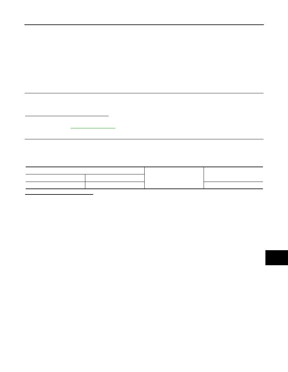
2.
Check voltage between combination meter harness connector and ground.
Is the inspection result normal?
YES
>> Replace combination meter.
NO
>> Inspect the power supply circuit. Refer to
PG-67, "Wiring Diagram - IGNITION POWER SUPPLY -
Terminals
Condition
Voltage (Approx.)
(+)
(–)
Combination meter
harness connector
Terminal
M34
2
Ground
When the ignition switch is in
ON position
Battery voltage
CHG
L TERMINAL CIRCUIT (SHORT)
CHG-13
< DTC/CIRCUIT DIAGNOSIS >
C
D
E
F
G
H
I
J
K
L
B
A
O
P
N
L TERMINAL CIRCUIT (SHORT)
Description
INFOID:0000000005514988
The “L” terminal circuit controls the charge warning lamp. The charge warning lamp illuminates when the igni-
tion switch is set to ON or START. When the alternator is providing sufficient voltage with the engine running,
the charge warning lamp will go off. If the charge warning lamp illuminates with the engine running, a malfunc-
tion is indicated.
Diagnosis Procedure
INFOID:0000000005514989
1.
CHECK “L” TERMINAL CIRCUIT (SHORT)
1.
Turn ignition switch OFF.
2.
Disconnect alternator connector.
3.
Turn ignition switch ON.
Does charge warning lamp illuminate?
YES
>> GO TO 2.
NO
>> Refer to
.
2.
CHECK HARNESS CONTINUITY (SHORT CIRCUIT)
1.
Turn the ignition switch OFF.
2.
Disconnect the battery cable from the negative terminal.
3.
Disconnect combination meter connector.
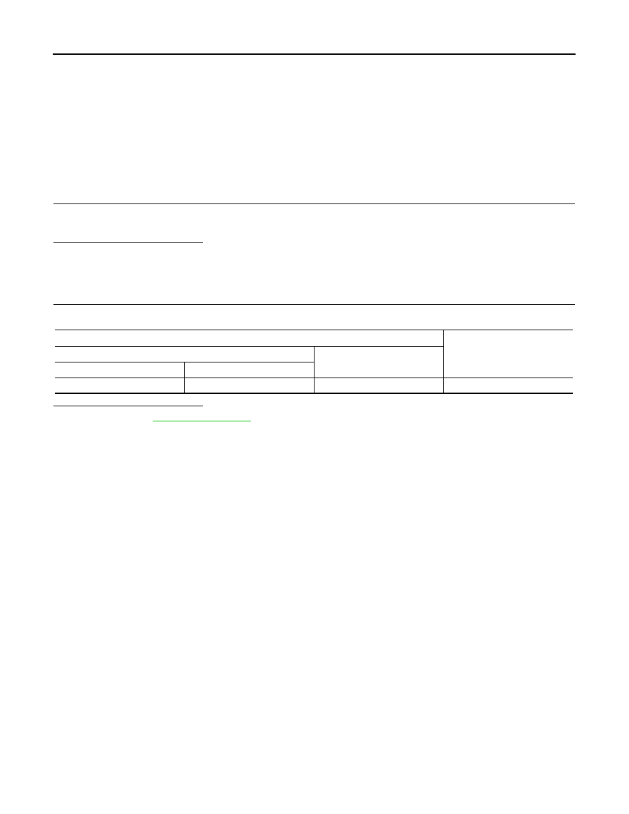
4.
Check continuity between combination meter harness connector and ground.
Is the inspection result normal?
YES
>> Replace combination meter.
NO
>> Repair the harness.
Combination meter harness connector
Ground
Continuity
Connector No.
Terminal No.
M34
25
Not existed
CHG-14
< DTC/CIRCUIT DIAGNOSIS >
S TERMINAL CIRCUIT
S TERMINAL CIRCUIT
Description
INFOID:0000000005514990
The output voltage of the alternator is controlled by the IC voltage regulator at the “S” terminal detecting the
input voltage.
The “S” terminal circuit detects the battery voltage to adjust the alternator output voltage with the IC voltage
regulator.
Diagnosis Procedure
INFOID:0000000005514991
1.
CHECK “S” TERMINAL CONNECTION
1.
Turn ignition switch OFF.
2.
Check if “S” terminal is clean and tight.
Is the inspection result normal?
YES
>> GO TO 2.
NO
>> Repair “S” terminal connection. Confirm repair by performing complete Starting/Charging system
test. Refer to Technical Service Bulletin.
2.
CHECK “S” TERMINAL CIRCUIT
Check voltage between alternator harness connector and ground.
Is the inspection result normal?
YES
>> Refer to
.
NO
>> Check harness for open between alternator and fuse.
Terminals
Voltage (Approx.)
(+)
(–)
Alternator harness connector
Terminal
F60
4
Ground
Battery voltage
Нет комментариевНе стесняйтесь поделиться с нами вашим ценным мнением.
Текст