Nissan Murano Z51. Instruction — part 338
CHG
DIAGNOSIS AND REPAIR WORKFLOW
CHG-3
< BASIC INSPECTION >
C
D
E
F
G
H
I
J
K
L
B
A
O
P
N
BASIC INSPECTION
DIAGNOSIS AND REPAIR WORKFLOW
Work Flow
INFOID:0000000005514975
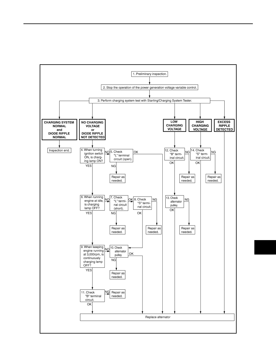
OVERALL SEQUENCE
DETAILED FLOW
JSMIA0009GB
CHG-4
< BASIC INSPECTION >
DIAGNOSIS AND REPAIR WORKFLOW
NOTE:
To ensure a complete and thorough diagnosis, the battery, starter and alternator test segments must be done
as a set from start to finish.
1.
PRELIMINARY INSPECTION
Perform the preliminary inspection. Refer to
CHG-24, "Inspection Procedure"
.
>> GO TO 2.
2.
STOP POWER GENERATION VOLTAGE VARIABLE CONTROL SYSTEM
Stop the operation of the power generation voltage variable control in either of the following procedures.
• After selecting “ENGINE” of “SELECT SYSTEM” using CONSULT-III, set the DUTY value of “ALTERNATOR
DUTY” to 0 % by selecting “ALTERNATOR DUTY” of “Active Test”. Continue “Active Test” until the end of
inspection. (When the DUTY value is 0 or 100 %, the normal power generation is performed according to the
characteristic of the IC voltage regulator of the alternator.)
• Turn the ignition switch OFF, and disconnect the battery current sensor connector. [However, DTC (P1550 -
P1554) of the engine might remain. After finishing the inspection, connect the battery current sensor connec-
tor and erase the self-diagnostic results history of the engine using CONSULT-III.]
>> GO TO 3.
3.
DIAGNOSIS WITH STARTING/CHARGING SYSTEM TESTER
Perform the charging system test using Starting/Charging System Tester (SST: J-44373). For details and oper-
ating instructions, refer to Technical Service Bulletin.
Test result
CHARGING SYSTEM NORMAL>>Charging system is normal and will also show “DIODE RIPPLE” test
result.
NO CHARGING VOLTAGE>>GO TO 4.
LOW CHARGING VOLTAGE>>GO TO 12.
HIGH CHARGING VOLTAGE>>GO TO 14.
DIODE RIPPLE NORMAL>>Diode ripple is OK and will also show “CHARGING VOLTAGE” test result.
EXCESS RIPPLE DETECTED>>Replace the alternator. Perform “DIODE RIPPLE” test again using Starting/
Charging System Tester (SST: J-44373) to confirm repair.
DIODE RIPPLE NOT DETECTED>>GO TO 4.
4.
INSPECTION WITH CHARGE WARNING LAMP (IGNITION SWITCH IS ON)
Turn the ignition switch ON.
Does the charge warning lamp illuminate?
YES
>> GO TO 6.
NO
>> GO TO 5.
5.
“L” TERMINAL CIRCUIT (OPEN) INSPECTION
Check “L” terminal circuit (open). Refer to
Is the “L” terminal circuit normal?
YES
>> Replace alternator.
NO
>> Repair as needed.
6.
INSPECTION WITH CHARGE WARNING LAMP (IDLING)
Start the engine and run it at idle.
Does the charge warning lamp turn OFF?
YES
>> GO TO 9.
NO
>> GO TO 7.
7.
“L” TERMINAL CIRCUIT (SHORT) INSPECTION
Check “L” terminal circuit (short). Refer to
Is the “L” terminal circuit normal?
YES
>> GO TO 8.
NO
>> Repair as needed.
CHG
DIAGNOSIS AND REPAIR WORKFLOW
CHG-5
< BASIC INSPECTION >
C
D
E
F
G
H
I
J
K
L
B
A
O
P
N
8.
“S” TERMINAL CIRCUIT INSPECTION
Check “S” terminal circuit. Refer to
Is the “S” terminal circuit normal?
YES
>> GO TO 10.
NO
>> Repair as needed.
9.
INSPECTION WITH CHARGE WARNING LAMP (ENGINE AT 3,000 RPM)
Increase and maintain the engine speed at 3,000 rpm.
Does the charge warning lamp remain off?
YES
>> GO TO 11.
NO
>> GO TO 10.
10.
INSPECTION OF ALTERNATOR PULLEY
Check alternator pulley. Refer to
Is alternator pulley normal?
YES
>> Replace alternator.
NO
>> Repair as needed.
11.
“B” TERMINAL CIRCUIT INSPECTION
Check “B” terminal circuit. Refer to
Is “B” terminal circuit normal?
YES
>> Replace alternator.
NO
>> Repair as needed.
12.
“B” TERMINAL CIRCUIT INSPECTION
Check “B” terminal circuit. Refer to
Is “B” terminal circuit normal?
YES
>> GO TO 13.
NO
>> Repair as needed.
13.
INSPECTION OF ALTERNATOR PULLEY
Check alternator pulley. Refer to
Is alternator pulley normal?
YES
>> Replace alternator.
NO
>> Repair as needed.
14.
“S” TERMINAL CIRCUIT INSPECTION
Check “S” terminal circuit. Refer to
Is the “S” terminal circuit normal?
YES
>> Replace alternator.
NO
>> Repair as needed.
CHG-6
< SYSTEM DESCRIPTION >
CHARGING SYSTEM
SYSTEM DESCRIPTION
CHARGING SYSTEM
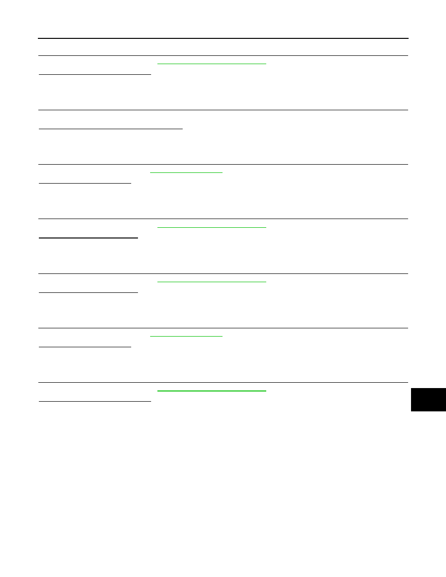
System Diagram
INFOID:0000000005514976
System Description
INFOID:0000000005514977
The voltage output is controlled by the IC voltage regulator.
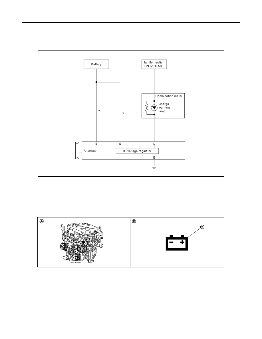
Component Parts Location
INFOID:0000000005514978
Component Description
INFOID:0000000005514979
JPMIA0426GB
1.
Alternator
2.
Charge warning lamp
A.
Cylinder block left side
B.
Combination meter
JPLIA0887ZZ
Нет комментариевНе стесняйтесь поделиться с нами вашим ценным мнением.
Текст