Nissan Pathfinder (2012 year). Instruction — part 475
MWI
DIAGNOSIS SYSTEM (METER)
MWI-25
< SYSTEM DESCRIPTION >
C
D
E
F
G
H
I
J
K
L
M
B
A
O
P
DIAGNOSIS SYSTEM (METER)
Diagnosis Description
INFOID:0000000007347467
SELF-DIAGNOSIS MODE
The following items can be checked during Combination Meter Self-Diagnosis Mode.
• Gauge sweep and present gauge values.
• Illuminates all odometer/trip meters and A/T indicator segments.
• Illuminates all micro controlled lamps/LEDs regardless of switch position.
• Displays estimated present battery voltage.
• Displays seat belt buckle switch LH status.
OPERATION PROCEDURE
NOTE:
• Once entered, combination meter self-diagnosis mode will function with the ignition switch in ON or START.
Combination meter self-diagnosis mode will exit upon turning the ignition switch to OFF or ACC.
• If the diagnosis function is activated with trip A displayed, the mileage on trip A is reset to 0000.0. (Trip B
operates the same way.)
To initiate combination meter self-diagnosis mode, refer to the following procedure.
1. Turn the ignition switch ON, while pressing the odometer/trip meter switch for 5 - 8 seconds. When the
diagnosis function is activated, the odometer/trip meter will display tESt.
NOTE:
Check combination meter power supply and ground circuit when self-diagnosis mode of combination meter
does not start. Refer to
MWI-31, "COMBINATION METER : Diagnosis Procedure"
. Replace combination
meter if normal. Refer to
MWI-89, "Removal and Installation"
.
COMBINATION METER SELF-DIAGNOSIS MODE FUNCTIONS
To interpret combination meter self-diagnosis mode functions, refer to the following table.
Event
Odometer Display
Description of Test/Data
Notes:
Odometer/trip meter A/B
switch held from 5 to 8
seconds (or until re-
leased)
tESt
Initiating self-diagnosis mode
Switch released
GAGE
Performs sweep of all
gauges, then displays
present gauge values.
Gauges sweep within 10 seconds
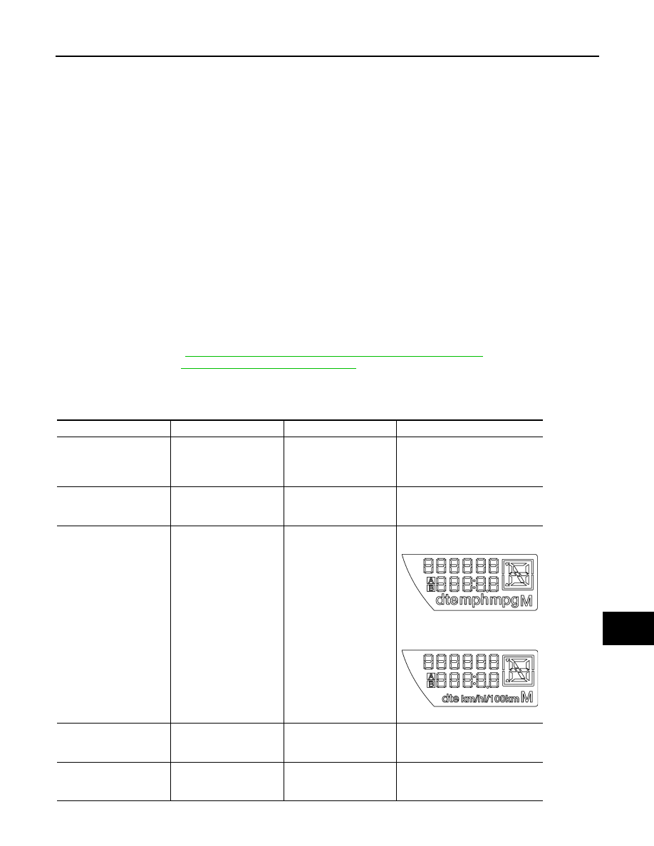
Switch pressed
(All segments illuminated)
Lights all LCD segments.
Compare with picture.
USA
Except USA
Switch pressed
bulb
Illuminates all micro-con-
trolled lamps/LEDs.
Part may not be configured for all
lamps (functions) that turn on dur-
ing test. This is normal.
Switch pressed
r XXXX, FAIL
Return to normal opera-
tion of all lamps/LEDs and
displays “r XXXX”.
If a malfunction exists, “FAIL” will
flash.
AWNIA0219ZZ
AWNIA0220ZZ
August 2012
2012 Pathfinder

MWI-26
< SYSTEM DESCRIPTION >
DIAGNOSIS SYSTEM (METER)
Switch pressed
nrXXXX
Displays Hex ROM rev as
stored in NVM.
Switch pressed
EE XX, FAIL
Displays “EE XX”.
If a malfunction exists, “FAIL” will
flash.
Switch pressed
dtXXXX
Hex coding of final manu-
facturing test date.
Switch pressed
(3 times)
Sc1 XX through Epr XX
Displays 8 bit software
configuration value in Hex
format
Switch pressed
1nF XX
Displays 8-bit market info
value in Hex format.
$31 = USA
$2A = Canada
$23 = EUR-R
$1C = EUR-L
$38 = Japan
$15 = Australia
$0E = Middle East
$FF = Other
Switch pressed
(3 times)
cYL XX through tF
N/A
Switch pressed
ot1 XX
Displays oil pressure tell-
tale “” in Hex format.
Switch pressed
ot0 XX
Displays oil pressure tell-
tale “” in Hex format.
Switch pressed
XXXXX
“Corrected” speed value
in hundredths of MPH.
Gauge indication may be
slightly higher. This is nor-
mal.
Will display “-----” if message is not
received. Will display “99999” if
data received is invalid.
Switch pressed
XXXXX
“Corrected” speed value
in hundredths of KPH.
Gauge indication may be
slightly different. This is
normal.
Will display “-----” if message is not
received. Will display “99999” if
data received is invalid.
Switch pressed
t XXXX
Tachometer value in
RPM. Gauge indication
may be higher at higher
RPM. This is normal.
Will display “-----” if message is not
received.
Switch pressed
F1XXXX
Present fuel level A/D in-
put. This input represents
fuel sender input.
000-009 = Short circuit
010-254 = Normal range
255 = Open circuit
Switch pressed
XXXC
Last temperature gauge
input value in degrees C.
Temperature gauge indi-
cates present tempera-
ture per indication
standard.
Will display “---”C if message is not
received.
Will display “999” if data received
is invalid.
High = 130 deg C
Normal = 70 - 105 deg C
Low = less than 50 deg C
Switch pressed
BAtXX.X
Estimated present battery
voltage.
Switch pressed
rES -X
Seat belt buckle switch LH
status.
1= Buckled
0 = Unbuckled
Switch pressed
(30 times)
PA -XX through PA1-XX
N/A
Switch pressed
GAGE
Return to beginning of self-diagno-
sis cycle.
Event
Odometer Display
Description of Test/Data
Notes:
August 2012
2012 Pathfinder

MWI
DIAGNOSIS SYSTEM (METER)
MWI-27
< SYSTEM DESCRIPTION >
C
D
E
F
G
H
I
J
K
L
M
B
A
O
P
CONSULT Function (METER/M&A)
INFOID:0000000007347468
CONSULT can display each diagnostic item using the diagnostic test modes shown following.
SELF-DIAG RESULTS
Display Item List
.
DATA MONITOR
Display Item List
X: Applicable
METER/M&A diagnosis mode
Description
SELF DIAGNOSTIC RESULTS
Displays combination meter self-diagnosis results.
DATA MONITOR
Displays combination meter input/output data in real time.
CAN DIAG SUPPORT MNTR
The result of transmit/receive diagnosis of CAN communication can be read.
Display item [Unit]
MAIN
SIGNALS
SELECTION
FROM MENU
Description
SPEED METER [km/h] or [mph]
X
X
Displays the value of vehicle speed signal.
SPEED OUTPUT [km/h] or [mph]
X
X
Displays the value of vehicle speed signal, which is transmitted to
each unit with CAN communication.
TACHO METER [rpm]
X
X
Displays the value of engine speed signal, which is input from ECM.
W TEMP METER [
°
C] or [
°
F]
X
X
Displays the value of engine coolant temperature signal, which is in-
put from ECM.
FUEL METER [lit.]
X
X
Displays the value, which processes a resistance signal from fuel
gauge.
DISTANCE [km] or [mile]
X
X
Displays the value, which is calculated by vehicle speed signal, fuel
gauge and fuel consumption from ECM.
FUEL W/L [ON/OFF]
X
X
Displays [ON/OFF] condition of low-fuel warning lamp.
C-ENG W/L [ON/OFF]
X
Displays [ON/OFF] condition of malfunction indicator lamp.
AIR PRES W/L [ON/OFF]
X
Displays [ON/OFF] condition of tire pressure warning lamp.
SEAT BELT W/L [ON/OFF]
X
Indicates [ON/OFF] condition of seat belt warning lamp.
BUZZER [ON/OFF]
X
X
Displays [ON/OFF] condition of buzzer.
DOOR W/L [ON/OFF]
X
Displays [ON/OFF] condition of door ajar warning lamp.
HI-BEAM IND [ON/OFF]
X
Displays [ON/OFF] condition of high beam indicator.
TURN IND [ON/OFF]
X
Displays [ON/OFF] condition of turn indicator.
OIL W/L [ON/OFF]
X
Displays [ON/OFF] condition of oil pressure warning lamp.
VDC/TCS IND [ON/OFF]
X
Displays [ON/OFF] condition of VDC OFF indicator lamp.
ABS W/L [ON/OFF]
X
Displays [ON/OFF] condition of ABS warning lamp.
SLIP IND [ON/OFF]
X
Displays [ON/OFF] condition of SLIP indicator lamp.
BRAKE W/L [ON/OFF]
X
Displays [ON/OFF] condition of brake warning lamp.*
KEY G/Y W/L [ON/OFF]
X
Displays [ON/OFF] condition of key green warning lamp.
KEY R W/L [ON/OFF]
X
Displays [ON/OFF] condition of key red warning lamp.
KEY KNOB W/L [ON/OFF]
X
Displays [ON/OFF] condition of key knob warning lamp.
M RANGE SW [ON/OFF]
X
X
Displays [ON/OFF] condition of instruction mode range switch.
NM RANGE SW [ON/OFF]
X
X
Displays [ON/OFF] condition of except for instruction mode range
switch.
AT SFT UP SW [ON/OFF]
X
X
Displays [ON/OFF] condition of A/T shift-up switch.
AT SFT DWN SW [ON/OFF]
X
X
Displays [ON/OFF] condition of A/T shift-down switch.
O/D OFF SW [ON/OFF]
X
Indicates [ON/OFF] condition of O/D OFF switch.
August 2012
2012 Pathfinder

MWI-28
< SYSTEM DESCRIPTION >
DIAGNOSIS SYSTEM (METER)
NOTE:
Some items are not available due to vehicle specification.
*: The monitor will indicate “OFF” even though the brake warning lamp is on if either of the following conditions exist.
• The parking brake is engaged
• The brake fluid level is low
BRAKE SW [ON/OFF]
X
Indicates [ON/OFF] condition of parking brake switch.
AT-M IND [ON/OFF]
X
X
Indicates [ON/OFF] condition of A/T instruction mode indicator.
AT-M GEAR [1, 2, 3, 4]
X
X
Indicates [1, 2, 3, 4] condition of A/T instruction mode gear position.
P RANGE IND [ON/OFF]
X
X
Indicates [ON/OFF] condition of A/T shift P range indicator.
R RANGE IND [ON/OFF]
X
X
Indicates [ON/OFF] condition of A/T shift R range indicator.
N RANGE IND [ON/OFF]
X
X
Indicates [ON/OFF] condition of A/T shift N range indicator.
D RANGE IND [ON/OFF]
X
X
Indicates [ON/OFF] condition of A/T shift D range indicator.
4 RANGE IND [ON/OFF]
X
X
Indicates [ON/OFF] condition of A/T shift 4 range indicator.
3 RANGE IND [ON/OFF]
X
X
Indicates [ON/OFF] condition of A/T shift 3 range indicator.
2 RANGE IND [ON/OFF]
X
X
Indicates [ON/OFF] condition of A/T shift 2 range indicator.
1 RANGE IND [ON/OFF]
X
X
Indicates [ON/OFF] condition of A/T shift 1 range indicator.
O/D OFF W/L [ON/OFF]
X
Displays [ON/OFF] condition of AT CHECK (with instruction mode) or
O/D OFF (without instruction mode) warning lamp.
CRUISE IND [ON/OFF]
X
Displays [ON/OFF] condition of CRUISE indicator.
SET IND [ON/OFF]
X
Displays [ON/OFF] condition of SET indicator.
4WD LOCK SW [ON/OFF]
X
Indicates [ON/OFF] condition of 4WD lock switch.
4WD LOCK IND [ON/OFF]
X
Indicates [ON/OFF] condition of 4WD lock indicator.
FUEL CAP W/L [ON/OFF]
X
Displays [ON/OFF] condition of loose fuel cap indicator.
TPMS PRESS L [ON/OFF]
X
Displays [ON/OFF] condition of check tire pressure indicator.
Display item [Unit]
MAIN
SIGNALS
SELECTION
FROM MENU
Description
August 2012
2012 Pathfinder

MWI
DTC U1000 CAN COMMUNICATION
MWI-29
< DTC/CIRCUIT DIAGNOSIS >
C
D
E
F
G
H
I
J
K
L
M
B
A
O
P
DTC/CIRCUIT DIAGNOSIS
DTC U1000 CAN COMMUNICATION
DTC Logic
INFOID:0000000007347469
DTC DETECTION LOGIC
Diagnosis Procedure
INFOID:0000000007347470
Symptom: Displays “CAN COMM CIRC [U1000]” as a self-diagnosis result of combination meter.
1.
CHECK CAN COMMUNICATION
Select “SELF-DIAG RESULTS” mode for “METER/M&A” with CONSULT.
>> Go to “LAN system”. Refer to
LAN-14, "Trouble Diagnosis Flow Chart"
.
DTC
CONSULT display
Detection condition
U1000
CAN COMM CIRC
[U1000]
When combination meter is not receiving CAN communication signals for 2 seconds or more.
August 2012
2012 Pathfinder

MWI-30
< DTC/CIRCUIT DIAGNOSIS >
DTC B2205 VEHICLE SPEED CIRCUIT
DTC B2205 VEHICLE SPEED CIRCUIT
Description
INFOID:0000000007347471
The ABS actuator and electric unit (control unit) provides a vehicle speed signal to the combination meter via
CAN communication lines.
DTC Logic
INFOID:0000000007347472
Diagnosis Procedure
INFOID:0000000007347473
Symptom: Displays “VEHICLE SPEED CIRC [B2205]” as a self-diagnosis result of combination meter.
1.
CHECK COMBINATION METER INPUT SIGNAL
1. Start engine and select “METER/M&A” on CONSULT.
2. Using “SPEED METER” on “DATA MONITOR”, compare the value of DATA MONITOR with speedometer
pointer of combination meter. Speedometer and DATA MONITOR indications should be close.
Is the inspection result normal?
YES
>> Perform ABS actuator and electric unit (control unit) self-diagnosis. Refer to
(with Type 1) or
BRC-138, "CONSULT Function (ABS)"
(with Type 2).
NO
>> Replace combination meter. Refer to
MWI-89, "Removal and Installation"
DTC
CONSULT display
Detection condition
B2205
VEHICLE SPEED CIRC
[B2205]
Malfunction is detected when an erroneous speed signal is received for 2 seconds or more.
August 2012
2012 Pathfinder
MWI
POWER SUPPLY AND GROUND CIRCUIT
MWI-31
< DTC/CIRCUIT DIAGNOSIS >
C
D
E
F
G
H
I
J
K
L
M
B
A
O
P
POWER SUPPLY AND GROUND CIRCUIT
COMBINATION METER
COMBINATION METER : Diagnosis Procedure
INFOID:0000000007347474
Regarding Wiring Diagram information, refer to
.
1.
CHECK FUSES
Check for blown combination meter fuses.
Is the inspection result normal?
YES
>> GO TO 2
NO
>> If fuse is blown, be sure to eliminate cause of malfunction before installing new fuse.
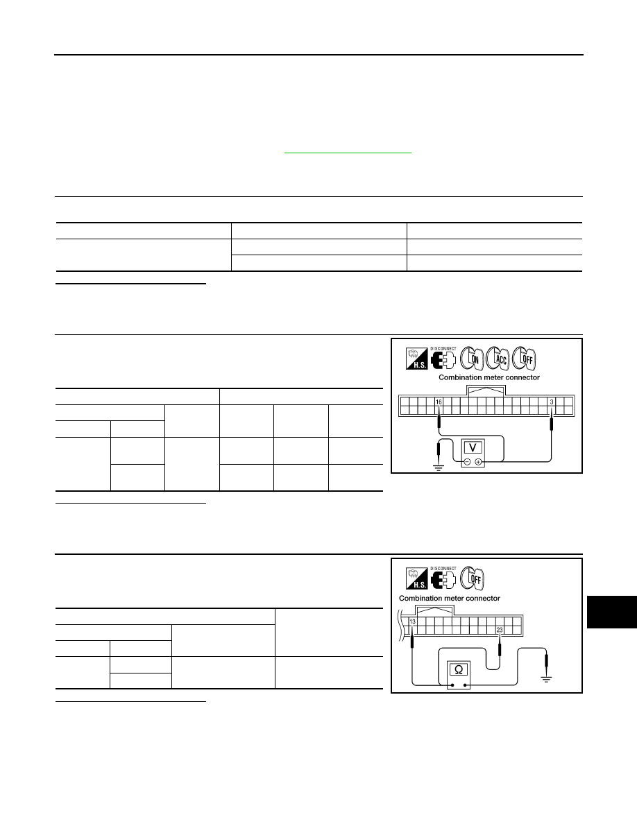
2.
POWER SUPPLY CIRCUIT CHECK
1. Disconnect combination meter connector M24.
2. Check voltage between combination meter harness connector
M24 terminals 3, 16 and ground.
Is the inspection result normal?
YES
>> GO TO 3
NO
>> Check harness for open between combination meter and fuse.
3.
GROUND CIRCUIT CHECK
1. Turn ignition switch OFF.
2. Check continuity between combination meter harness connector
M24 terminals 13, 23 and ground.
Is the inspection result normal?
YES
>> Inspection End.
NO
>> Check ground harness.
BCM (BODY CONTROL MODULE)
Unit
Power source
Fuse No.
Combination meter
Battery 19
Ignition switch ON or START
14
Terminals
Ignition switch position
(+)
(–)
OFF
ACC
ON
Connector
Terminal
M24
3
Ground
Battery
voltage
Battery
voltage
Battery
voltage
16
0V
0V
Battery
voltage
WKIA3279E
Terminals
Continuity
(+)
(–)
Connector
Terminal
M24
13
Ground
Yes
23
WKIA3280E
August 2012
2012 Pathfinder
MWI-32
< DTC/CIRCUIT DIAGNOSIS >
POWER SUPPLY AND GROUND CIRCUIT
BCM (BODY CONTROL MODULE) : Diagnosis Procedure
INFOID:0000000007830110
Regarding Wiring Diagram information, refer to
.
1.
CHECK FUSES AND FUSIBLE LINK
Check that the following fuses and fusible link are not blown.
Is the fuse blown?
YES
>> Replace the blown fuse or fusible link after repairing the affected circuit.
NO
>> GO TO 2
2.
CHECK POWER SUPPLY CIRCUIT
1. Turn ignition switch OFF.
2. Disconnect BCM.
3. Check voltage between BCM harness connector and ground.
Is the measurement value normal?
YES
>> GO TO 3
NO
>> Repair or replace harness.
3.
CHECK GROUND CIRCUIT
Check continuity between BCM harness connector and ground.
Does continuity exist?
YES
>> Inspection End.
NO
>> Repair or replace harness.
IPDM E/R (INTELLIGENT POWER DISTRIBUTION MODULE ENGINE ROOM)
Terminal No.
Signal name
Fuses and fusible link No.
57
Battery power supply
21 (10A)
70
G (50A)
11
Ignition ACC or ON
4 (10A)
38
Ignition ON or START
1 (10A)
Connector
Terminals
Power
source
Condition
Voltage (V) (Ap-
prox.)
(+)
(-)
M18
11
Ground
ACC
power
supply
Ignition
switch
ACC or
ON
Battery voltage
38
Ground
Ignition
power
supply
Ignition
switch ON
or START
Battery voltage
M20
57
Ground
Battery
power
supply
Ignition
switch
OFF
Battery voltage
70
Ground
Battery
power
supply
Ignition
switch
OFF
Battery voltage
LIIA2415E
BCM
Ground
Continuity
Connector
Terminal
M20
67
Yes
LIIA0915E
August 2012
2012 Pathfinder
Нет комментариевНе стесняйтесь поделиться с нами вашим ценным мнением.
Текст