Nissan Pathfinder (2012 year). Instruction — part 473
MWI
METER SYSTEM
MWI-9
< SYSTEM DESCRIPTION >
C
D
E
F
G
H
I
J
K
L
M
B
A
O
P
SPEEDOMETER : Component Description
INFOID:0000000007347429
TACHOMETER
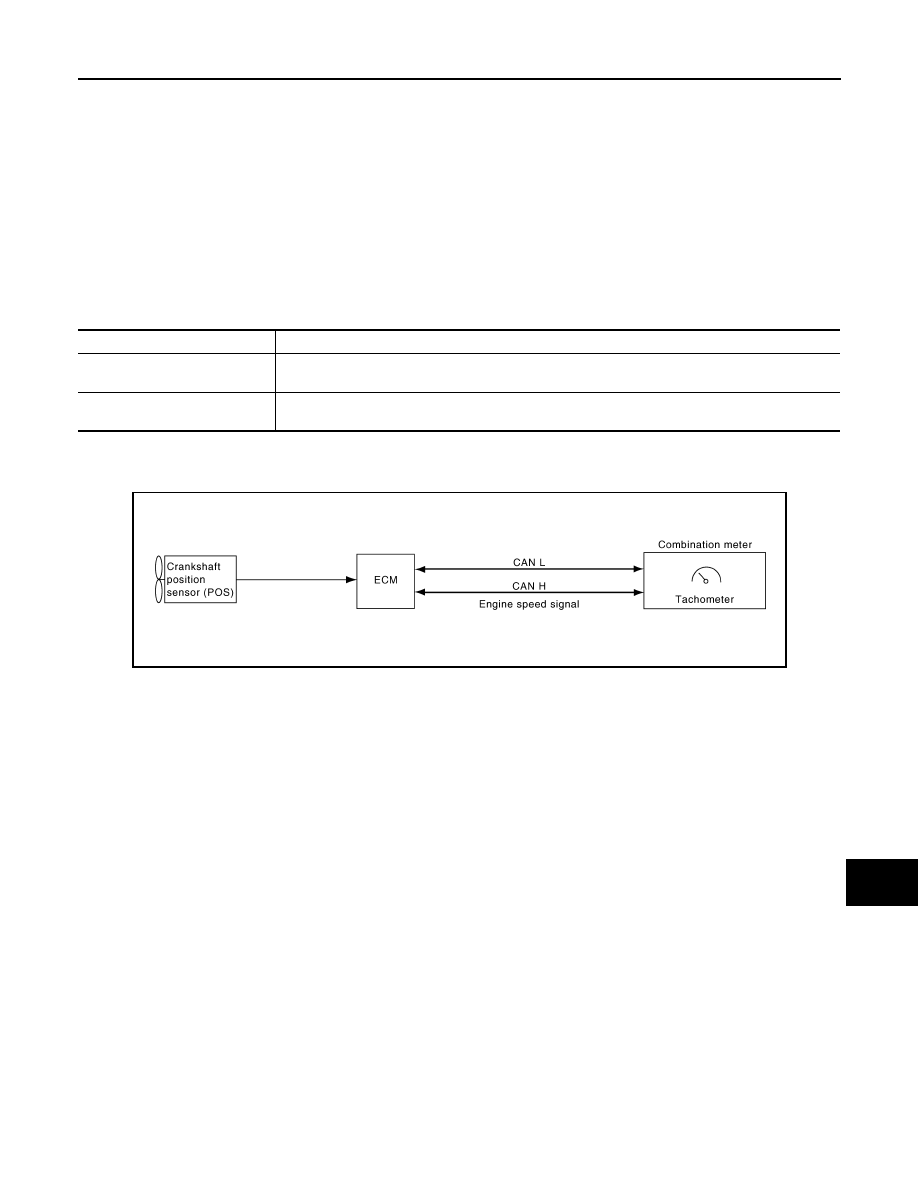
TACHOMETER : System Diagram
INFOID:0000000007347430
TACHOMETER : System Description
INFOID:0000000007347431
The tachometer indicates engine speed in revolutions per minute (rpm).
The ECM provides an engine speed signal to the combination meter via CAN communication lines.
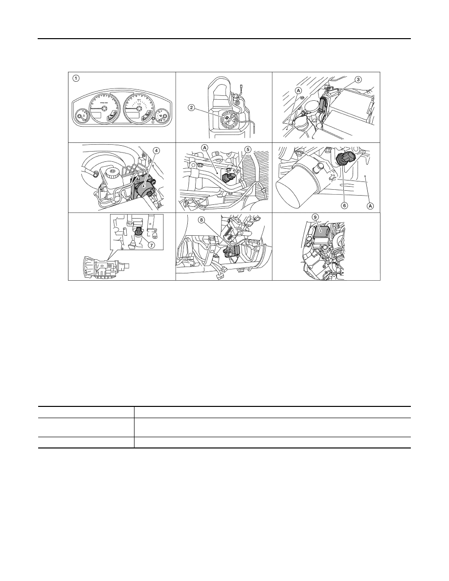
1.
Combination meter M24
2.
Fuel level sensor unit and fuel pump C5
(view with fuel tank removed)
3.
ECM (view with ECM cover removed)
E7 (with VK56DE)
E16 (with VQ40DE)
A. Coolant reservoir
4.
ABS actuator and electric unit (control
unit)
E125 (with VQ40DE)
E127 (with VK56DE)
5.
Oil pressure switch E208 (with VQ40DE)
A. Oil pan (upper)
6.
Oil pressure switch F4 (with VK56DE)
A: Oil pan (upper)
7.
A/T assembly F9
8.
BCM M18, M19 (view with instrument
lower panel LH removed)
9.
IPDM E/R E122, E124
Unit
Description
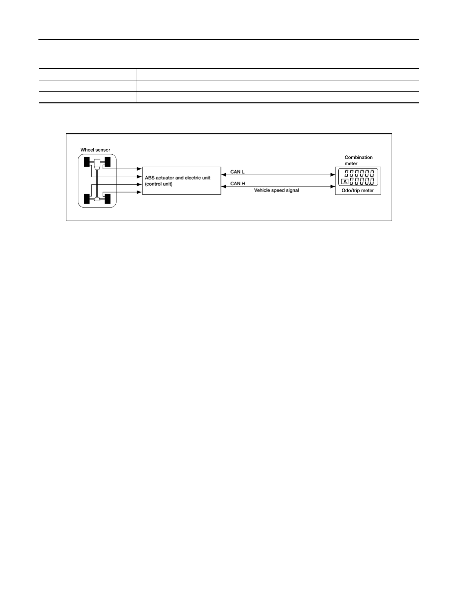
Combination meter
Indicates the vehicle speed according to the vehicle speed signal received from ABS actuator and
electric unit (control unit) via CAN communication.
ABS actuator and electric unit
(control unit)
Transmits the vehicle speed signal to the combination meter with CAN communication line.
SKIB6904E
August 2012
2012 Pathfinder
MWI-10
< SYSTEM DESCRIPTION >
METER SYSTEM
TACHOMETER : Component Parts Location
INFOID:0000000007347432
TACHOMETER : Component Description
INFOID:0000000007347433
ENGINE COOLANT TEMPERATURE GAUGE
AWNIA0217ZZ
1.
Combination meter M24
2.
Fuel level sensor unit and fuel pump C5
(view with fuel tank removed)
3.
ECM (view with ECM cover removed)
E7 (with VK56DE)
E16 (with VQ40DE)
A. Coolant reservoir
4.
ABS actuator and electric unit (control
unit)
E125 (with VQ40DE)
E127 (with VK56DE)
5.
Oil pressure switch E208 (with VQ40DE)
A. Oil pan (upper)
6.
Oil pressure switch F4 (with VK56DE)
A: Oil pan (upper)
7.
A/T assembly F9
8.
BCM M18, M19 (view with instrument
lower panel LH removed)
9.
IPDM E/R E122, E124
Unit
Description
Combination meter
Indicates the engine speed in RPM according to the engine speed signal received from ECM via
CAN communication.
ECM
Transmits the engine speed signal to the combination meter with CAN communication line.
August 2012
2012 Pathfinder
MWI
METER SYSTEM
MWI-11
< SYSTEM DESCRIPTION >
C
D
E
F
G
H
I
J
K
L
M
B
A
O
P
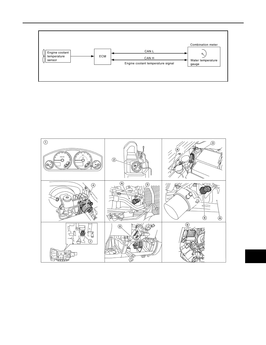
ENGINE COOLANT TEMPERATURE GAUGE : System Diagram
INFOID:0000000007347434
ENGINE COOLANT TEMPERATURE GAUGE : System Description
INFOID:0000000007347435
The engine coolant temperature gauge indicates the engine coolant temperature.
The ECM provides an engine coolant temperature signal to the combination meter via CAN communication
lines.
ENGINE COOLANT TEMPERATURE GAUGE : Component Parts Location
INFOID:0000000007347436
SKIB6905E
AWNIA0217ZZ
1.
Combination meter M24
2.
Fuel level sensor unit and fuel pump C5
(view with fuel tank removed)
3.
ECM (view with ECM cover removed)
E7 (with VK56DE)
E16 (with VQ40DE)
A. Coolant reservoir
4.
ABS actuator and electric unit (control
unit)
E125 (with VQ40DE)
E127 (with VK56DE)
5.
Oil pressure switch E208 (with VQ40DE)
A. Oil pan (upper)
6.
Oil pressure switch F4 (with VK56DE)
A: Oil pan (upper)
7.
A/T assembly F9
8.
BCM M18, M19 (view with instrument
lower panel LH removed)
9.
IPDM E/R E122, E124
August 2012
2012 Pathfinder
MWI-12
< SYSTEM DESCRIPTION >
METER SYSTEM
ENGINE COOLANT TEMPERATURE GAUGE : Component Description
INFOID:0000000007347437
FUEL GAUGE
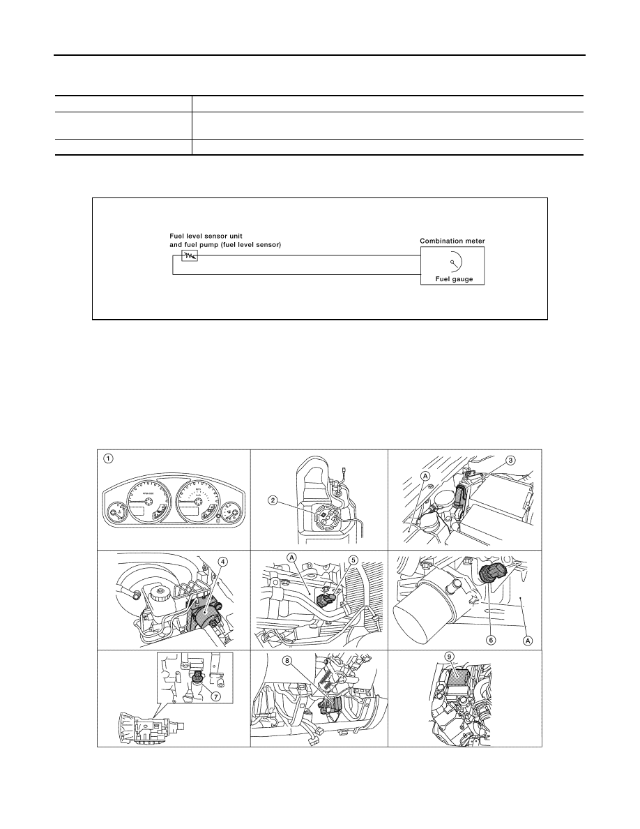
FUEL GAUGE : System Diagram
INFOID:0000000007347438
FUEL GAUGE : System Description
INFOID:0000000007347439
The fuel gauge indicates the approximate fuel level in the fuel tank.
The fuel gauge is regulated by the unified meter control unit and a variable resistor signal supplied by the fuel
level sensor unit.
FUEL GAUGE : Component Parts Location
INFOID:0000000007347440
Unit
Description
Combination meter
Indicates the engine coolant temperature according to the engine coolant temperature signal re-
ceived from ECM via CAN communication.
ECM
Transmits the engine coolant temperature signal to the combination meter via CAN communication.
AWNIA0004GB
AWNIA0217ZZ
August 2012
2012 Pathfinder
MWI
METER SYSTEM
MWI-13
< SYSTEM DESCRIPTION >
C
D
E
F
G
H
I
J
K
L
M
B
A
O
P
FUEL GAUGE : Component Description
INFOID:0000000007347441
ENGINE OIL PRESSURE GAUGE
ENGINE OIL PRESSURE GAUGE : System Diagram
INFOID:0000000007347442
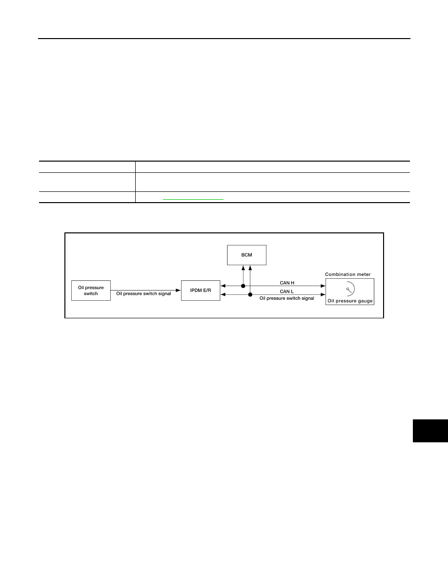
ENGINE OIL PRESSURE GAUGE : System Description
INFOID:0000000007347443
The engine oil pressure gauge indicates whether the engine oil pressure is low or normal.
The oil pressure gauge is controlled by the IPDM E/R. The IPDM E/R reads the ON/OFF signals from the oil
pressure switch and transmits the oil pressure switch signal to the combination meter via BCM with the CAN
communication line. The oil pressure gauge displays a low or normal indication according to the oil pressure
switch signal received via CAN communication.
1.
Combination meter M24
2.
Fuel level sensor unit and fuel pump C5
(view with fuel tank removed)
3.
ECM (view with ECM cover removed)
E7 (with VK56DE)
E16 (with VQ40DE)
A. Coolant reservoir
4.
ABS actuator and electric unit (control
unit)
E125 (with VQ40DE)
E127 (with VK56DE)
5.
Oil pressure switch E208 (with VQ40DE)
A. Oil pan (upper)
6.
Oil pressure switch F4 (with VK56DE)
A: Oil pan (upper)
7.
A/T assembly F9
8.
BCM M18, M19 (view with instrument
lower panel LH removed)
9.
IPDM E/R E122, E124
Unit
Description
Combination meter
Indicates the fuel level according to the fuel level sensor signal received from the fuel level sensor
unit.
Fuel level sensor unit
Refer to
.
AWNIA0174GB
August 2012
2012 Pathfinder
MWI-14
< SYSTEM DESCRIPTION >
METER SYSTEM
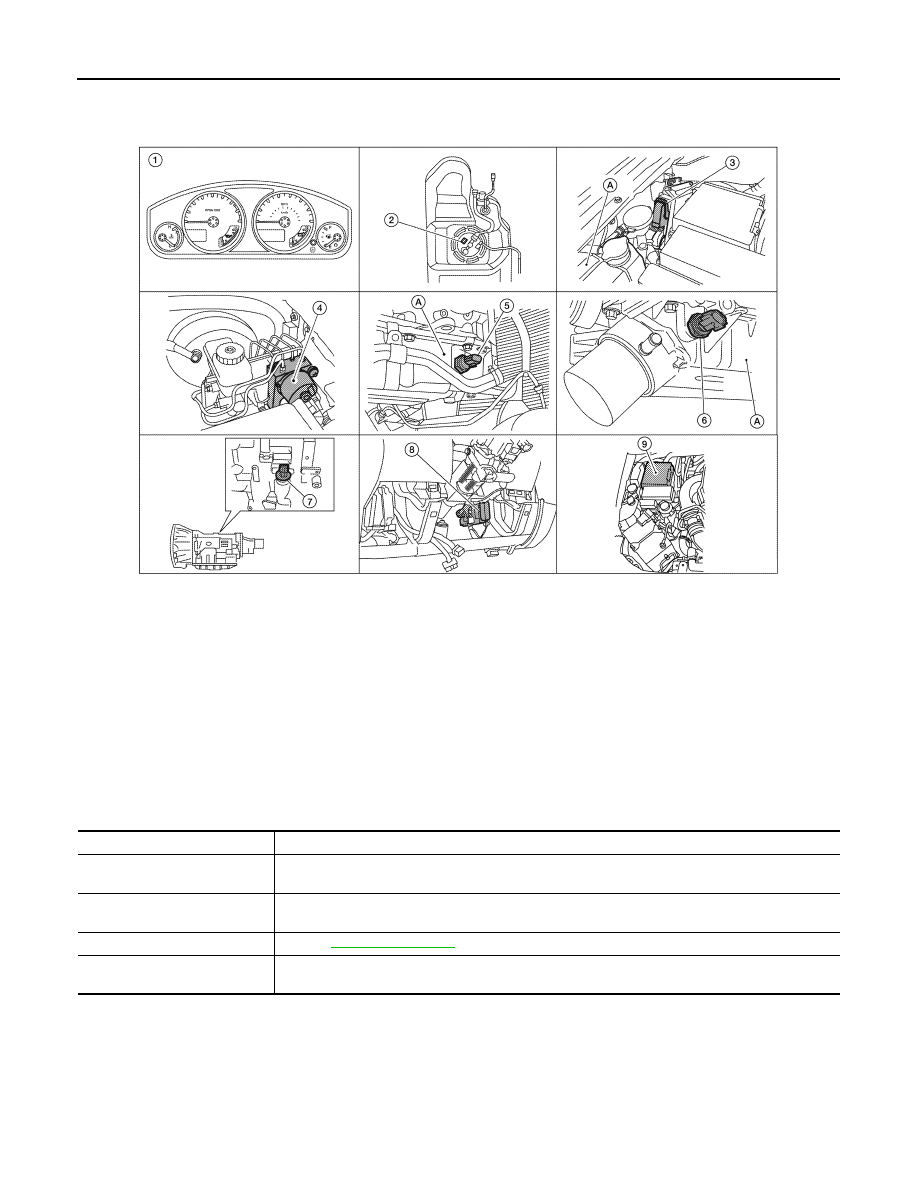
ENGINE OIL PRESSURE GAUGE : Component Parts Location
INFOID:0000000007347444
ENGINE OIL PRESSURE GAUGE : Component Description
INFOID:0000000007347445
VOLTAGE GAUGE
AWNIA0217ZZ
1.
Combination meter M24
2.
Fuel level sensor unit and fuel pump C5
(view with fuel tank removed)
3.
ECM (view with ECM cover removed)
E7 (with VK56DE)
E16 (with VQ40DE)
A. Coolant reservoir
4.
ABS actuator and electric unit (control
unit)
E125 (with VQ40DE)
E127 (with VK56DE)
5.
Oil pressure switch E208 (with VQ40DE)
A. Oil pan (upper)
6.
Oil pressure switch F4 (with VK56DE)
A: Oil pan (upper)
7.
A/T assembly F9
8.
BCM M18, M19 (view with instrument
lower panel LH removed)
9.
IPDM E/R E122, E124
Unit
Description
Combination meter
Indicates the engine oil pressure (low/normal) according to the oil pressure switch signal received
from BCM with CAN communication line.
IPDM E/R
Reads the ON/OFF signals from the oil pressure switch and transmits the oil pressure switch signal
to the combination meter via BCM with the CAN communication line.
Oil pressure switch
Refer to
.
BCM
Transmits the oil pressure switch signal received from IPDM E/R via CAN communication to the
combination meter via CAN communication.
August 2012
2012 Pathfinder
MWI
METER SYSTEM
MWI-15
< SYSTEM DESCRIPTION >
C
D
E
F
G
H
I
J
K
L
M
B
A
O
P
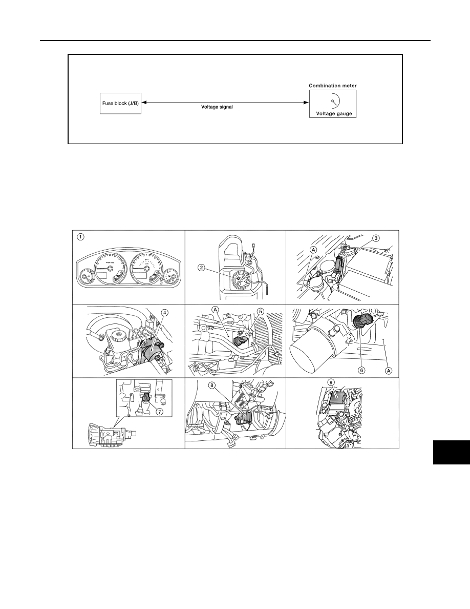
VOLTAGE GAUGE : System Diagram
INFOID:0000000007347446
VOLTAGE GAUGE : System Description
INFOID:0000000007347447
The voltage gauge indicates the battery/charging system voltage.
The voltage gauge is regulated by the unified meter control unit.
VOLTAGE GAUGE : Component Parts Location
INFOID:0000000007347448
AWNIA0106GB
AWNIA0217ZZ
1.
Combination meter M24
2.
Fuel level sensor unit and fuel pump C5
(view with fuel tank removed)
3.
ECM (view with ECM cover removed)
E7 (with VK56DE)
E16 (with VQ40DE)
A. Coolant reservoir
4.
ABS actuator and electric unit (control
unit)
E125 (with VQ40DE)
E127 (with VK56DE)
5.
Oil pressure switch E208 (with VQ40DE)
A. Oil pan (upper)
6.
Oil pressure switch F4 (with VK56DE)
A: Oil pan (upper)
7.
A/T assembly F9
8.
BCM M18, M19 (view with instrument
lower panel LH removed)
9.
IPDM E/R E122, E124
August 2012
2012 Pathfinder
MWI-16
< SYSTEM DESCRIPTION >
METER SYSTEM
VOLTAGE GAUGE : Component Description
INFOID:0000000007347449
ODO/TRIP METER
ODO/TRIP METER : System Diagram
INFOID:0000000007347450
ODO/TRIP METER : System Description
INFOID:0000000007347451
The vehicle speed signal and the memory signals from the meter memory circuit are processed by the combi-
nation meter and the mileage is displayed.
HOW TO CHANGE THE DISPLAY FOR ODO/TRIP METER
Refer to Owner's Instruction for odo/trip meter operating instructions.
LOOSE FUEL CAP WARNING
The LOOSE FUEL CAP indicator will display in the odometer when the fuel-filler cap is not tightened correctly.
The indicator will turn off as soon as the ECM detects the fuel-filler cap is properly tightened. The ECM pro-
vides a loose fuel cap signal to the combination meter via CAN communication lines.
CHECK TIRE PRESSURE WARNING
The CHECK TIRE PRESSURE indicator will display in the odometer when BCM has detected a low tire pres-
sure condition.
Unit
Description
Combination meter
Indicates the battery voltage according to the voltage signal received from the fuse block (J/B).
Fuse block (J/B)
Transmits the battery voltage signal to the combination meter.
AWNIA0005GB
August 2012
2012 Pathfinder
Нет комментариевНе стесняйтесь поделиться с нами вашим ценным мнением.
Текст