Nissan Pathfinder (2012 year). Instruction — part 364

EXL-28
< SYSTEM DESCRIPTION >
DIAGNOSIS SYSTEM (BCM)
HEADLAMP
HEADLAMP : CONSULT Function (BCM - HEAD LAMP)
INFOID:0000000007827520
DATA MONITOR
ACTIVE TEST
WORK SUPPORT
Monitor Item [Unit]
Description
IGN ON SW [On/Off]
Indicates condition of ignition switch ON position.
ACC ON SW [On/Off]
Indicates condition of ignition switch ACC position.
HI BEAM SW [On/Off]
Indicates condition of combination switch.
HEAD LAMP SW 1 [On/Off]
HEAD LAMP SW 2 [On/Off]
LIGHT SW 1ST [On/Off]
AUTO LIGHT SW [On/Off]
PASSING SW [On/Off]
FR FOG SW [On/Off]
DOOR SW-DR [On/Off]
Indicates condition of front door switch LH.
DOOR SW-AS [On/Off]
Indicates condition of front door switch RH.
DOOR SW-RR [On/Off]
Indicates condition of rear door switch RH.
DOOR SW-RL [On/Off]
Indicates condition of rear door switch LH.
BACK DOOR SW [On/Off]
Indicates condition of back door switch.
TURN SIGNAL R [On/Off]
Indicates condition of combination switch.
TURN SIGNAL L [On/Off]
OPTICAL SENSOR [V]
Indicates voltage signal from optical sensor.
Test Item
Description
TAIL LAMP
This test is able to check tail lamp operation [Off/On].
HEAD LAMP
This test is able to check head lamp operation [Off/Lo/Hi].
FR FOG LAMP
This test is able to check front fog lamp operation [Off/On].
Support Item
Setting
Description
BATTERY SAVER SET
Off
Exterior lamp battery saver function OFF.
On*
Exterior lamp battery saver function ON.
CUSTOM A/LIGHT SETTING
MODE4
Less sensitive setting than normal setting (Turns ON later than
normal operation).
MODE3
More sensitive setting than MODE 2 (Turns ON earlier than
MODE 2).
MODE2
More sensitive setting than normal setting (Turns ON earlier
than normal operation).
MODE1*
Normal.
August 2012
2012 Pathfinder

DIAGNOSIS SYSTEM (BCM)
EXL-29
< SYSTEM DESCRIPTION >
C
D
E
F
G
H
I
J
K
M
A
B
EXL
N
O
P
*: Initial setting
FLASHER
FLASHER : CONSULT Function (BCM - FLASHER)
INFOID:0000000007827521
DATA MONITOR
ACTIVE TEST
COMB SW
COMB SW : CONSULT Function (BCM - COMB SW)
INFOID:0000000007827522
DATA MONITOR
ILL DELAY SET
MODE8
180 sec
Sets delay timer function operation time
(All doors closed).
MODE7
150 sec
MODE6
120 sec
MODE5
90 sec
MODE4
60 sec
MODE3
30 sec
MODE2
OFF
MODE1*
45 sec
Support Item
Setting
Description
Monitor Item [Unit]
Description
IGN ON SW [On/Off]
Indicates condition of ignition switch ON position.
HAZARD SW [On/Off]
Indicates condition of hazard switch.
TURN SIGNAL R [On/Off]
Indicates condition of turn signal function of combination switch.
TURN SIGNAL L [On/Off]
BRAKE SW [On/Off]
Indicates condition of brake switch.
Test Item
Description
FLASHER
This test is able to check turn signal lamp operation [Off/LH/RH].
Monitor Item [Unit]
Description
TURN SIGNAL R [On/Off]
Indicates condition of turn signal operation of combination switch.
TURN SIGNAL L [On/Off]
HI BEAM SW [On/Off]
Indicates condition of hi beam operation of combination switch.
HEAD LAMP SW 1 [On/Off]
Indicates condition of headlamp operation of combination switch.
HEAD LAMP SW 2 [On/Off]
LIGHT SW 1ST [On/Off]
Indicates condition of lighting operation of combination switch.
PASSING SW [On/Off]
Indicates condition of passing switch operation of combination switch.
AUTO LIGHT SW [On/Off]
Indicates condition of auto light operation of combination switch.
FR FOG SW [On/Off]
Indicates condition of front fog light operation of combination switch.
FR WIPER HI [On/Off]
Indicates condition of front wiper operation of combination switch.
FR WIPER LOW [On/Off]
FR WIPER INT [On/Off]
FR WASHER SW [On/Off]
Indicates condition of front washer operation of combination switch.
INT VOLUME [1 - 7]
Indicates condition of intermittent wiper operation of combination switch.
August 2012
2012 Pathfinder

EXL-30
< SYSTEM DESCRIPTION >
DIAGNOSIS SYSTEM (BCM)
RR WIPER ON [On/Off]
Indicates condition of rear wiper operation of combination switch.
RR WIPER INT [On/Off]
RR WASHER SW [On/Off]
Indicates condition of rear washer operation of combination switch.
Monitor Item [Unit]
Description
August 2012
2012 Pathfinder
DIAGNOSIS SYSTEM (IPDM E/R)
EXL-31
< SYSTEM DESCRIPTION >
C
D
E
F
G
H
I
J
K
M
A
B
EXL
N
O
P
DIAGNOSIS SYSTEM (IPDM E/R)
Diagnosis Description
INFOID:0000000007827530
AUTO ACTIVE TEST
Description
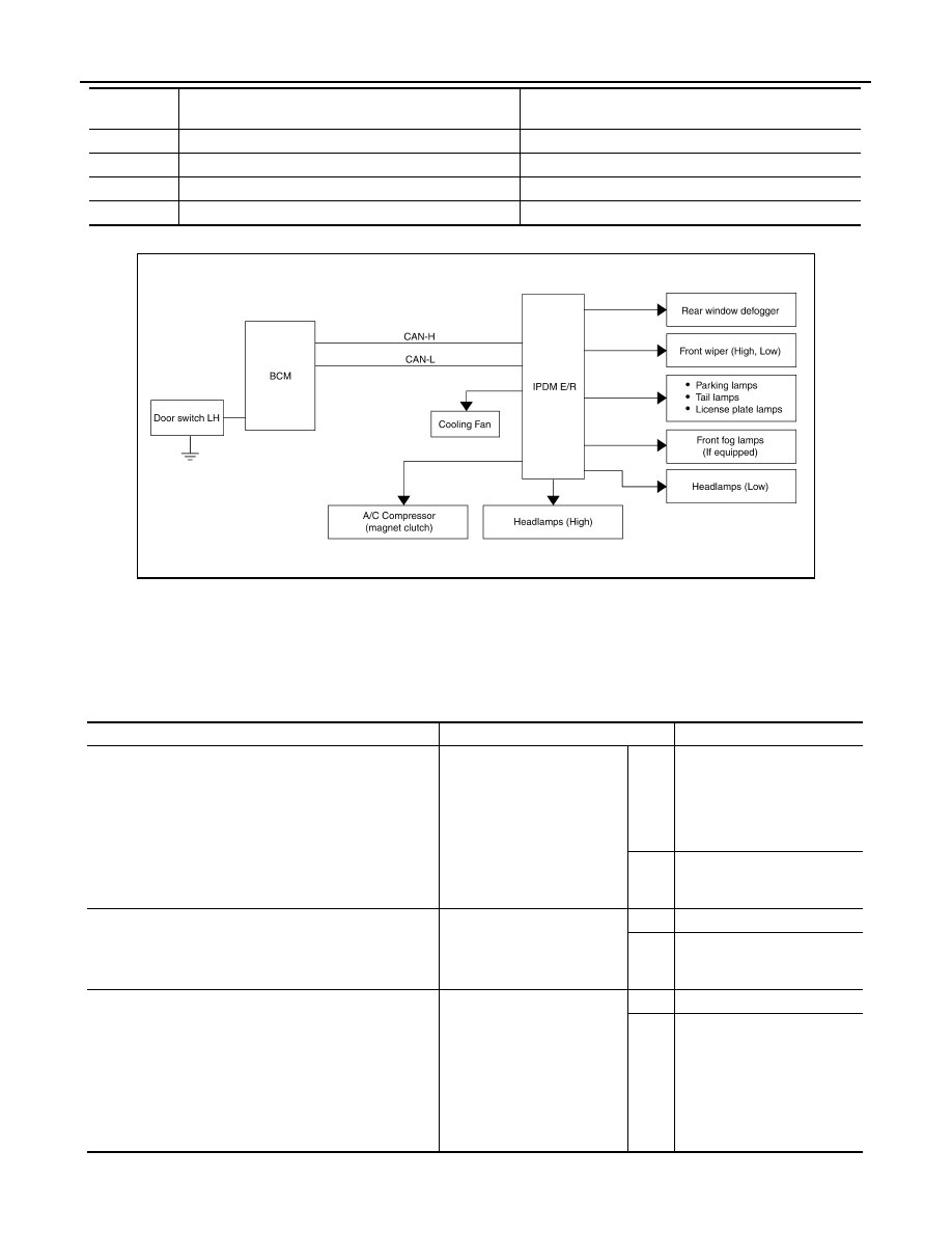
In auto active test mode, the IPDM E/R sends a drive signal to the following systems to check their operation.
• Oil pressure low warning indicator
• Oil pressure gauge
• Rear window defogger
• Front wipers
• Tail, license and parking lamps
• Front fog lamps (if equipped)
• Headlamps (Hi, Lo)
• A/C compressor (magnetic clutch)
• Cooling fan
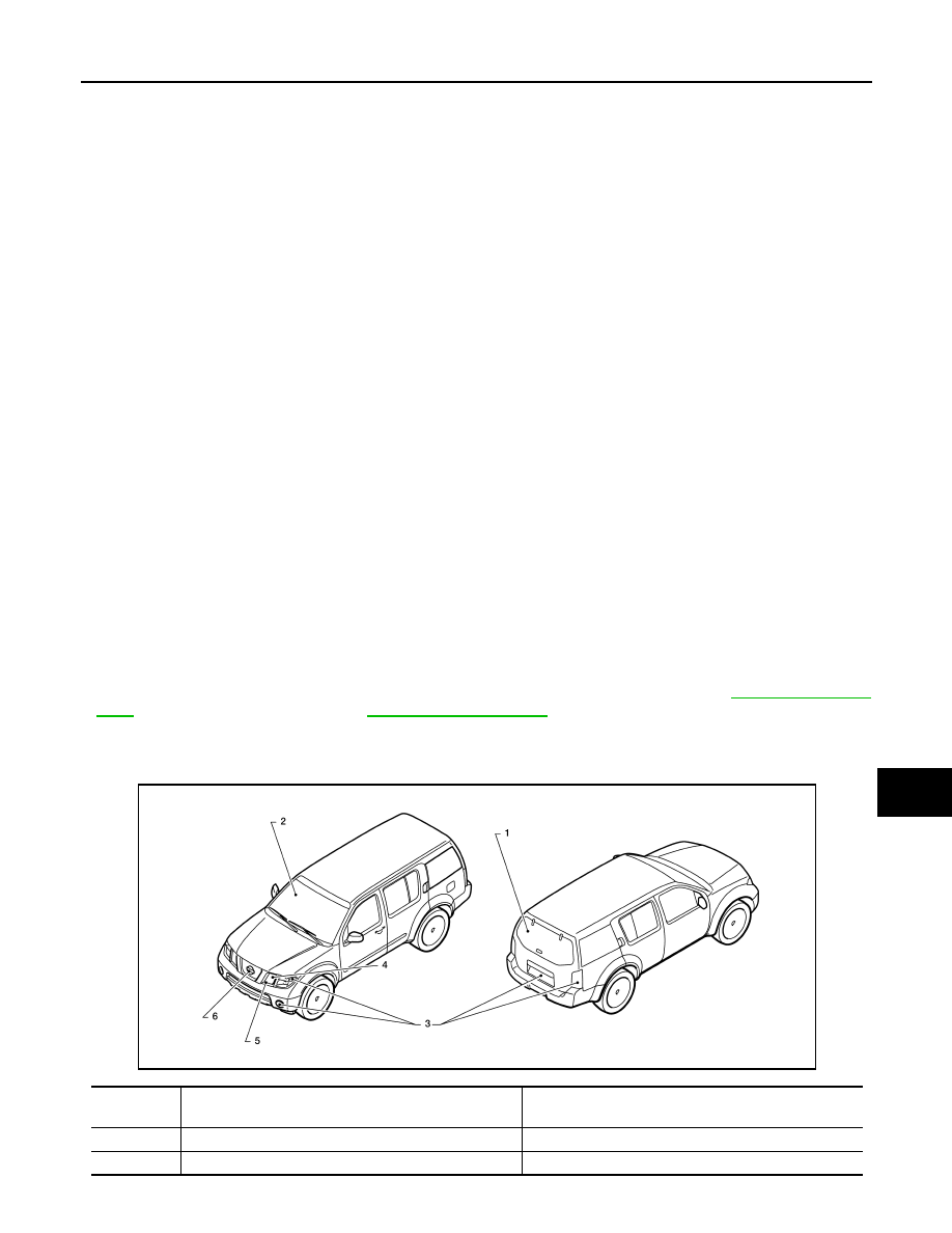
Operation Procedure
1. Close the hood and front door RH, and lift the wiper arms from the windshield (to prevent windshield dam-
age due to wiper operation).
NOTE:
When auto active test is performed with hood opened, sprinkle water on windshield before hand.
2. Turn ignition switch OFF.
3. Turn the ignition switch ON and, within 20 seconds, press the front door switch LH 10 times. Then turn the
ignition switch OFF.
4. Turn the ignition switch ON within 10 seconds. After that the horn sounds once and the auto active test
starts.
5. After a series of the following operations is repeated 3 times, auto active test is completed.
NOTE:
When auto active test mode has to be cancelled halfway through test, turn ignition switch OFF.
CAUTION:
• If auto active test mode cannot be actuated, check door switch system. Refer to
(with Intelligent Key system),
(without Intelligent Key system).
• Do not start the engine.
Inspection in Auto Active Test Mode
When auto active test mode is actuated, the following 7 steps are repeated 3 times.
Operation
sequence
Inspection Location
Operation
1
Rear window defogger
10 seconds
2
Front wipers
LO for 5 seconds
→
HI for 5 seconds
WKIA4991E
August 2012
2012 Pathfinder
EXL-32
< SYSTEM DESCRIPTION >
DIAGNOSIS SYSTEM (IPDM E/R)
Concept of auto active test
• IPDM E/R starts the auto active test with the door switch signals transmitted by BCM via CAN communica-
tion. Therefore, the CAN communication line between IPDM E/R and BCM is considered normal if the auto
active test starts successfully.
• The auto active test facilitates troubleshooting if any systems controlled by IPDM E/R cannot be operated.
Diagnosis chart in auto active test mode
3
Tail, license, front fog and parking lamps
10 seconds
4
Headlamps
LO for 10 seconds
→
HI on-off for 5 seconds
5
A/C compressor (magnetic clutch)
ON
⇔
OFF 5 times
6
Cooling fan
10 seconds
Operation
sequence
Inspection Location
Operation
AWMIA1124GB
Symptom
Inspection contents
Possible cause
Oil pressure low warning indicator does not operate
Perform auto active test.
Does the oil pressure low
warning indicator operate?
YES
• IPDM E/R signal input cir-
cuit
• ECM signal input circuit
• CAN communication signal
between ECM and combi-
nation meter
NO
• CAN communication signal
between IPDM E/R, BCM
and combination meter
Oil pressure gauge does not operate
Perform auto active test.
Does the oil pressure gauge
operate?
YES
IPDM E/R signal input circuit
NO
• CAN communication signal
between IPDM E/R, BCM
and combination meter
Rear window defogger does not operate
Perform auto active test.
Does the rear window defog-
ger operate?
YES
BCM signal input circuit
NO
• Harness or connector be-
tween A/C and AV switch
assembly and AV control
unit
• CAN communication signal
between BCM and IPDM E/
R
August 2012
2012 Pathfinder

DIAGNOSIS SYSTEM (IPDM E/R)
EXL-33
< SYSTEM DESCRIPTION >
C
D
E
F
G
H
I
J
K
M
A
B
EXL
N
O
P
CONSULT Function (IPDM E/R)
INFOID:0000000007827531
APPLICATION ITEM
CONSULT performs the following functions via CAN communication with IPDM E/R.
SELF DIAGNOSTIC RESULT
.
DATA MONITOR
Any of the following components do not operate
• Front wipers
• Tail lamps
• License plate lamps
• Parking lamps
• Front fog lamps (if equipped)
• Headlamps (Hi, Lo)
Perform auto active test.
Does the applicable system
operate?
YES
BCM signal input system
NO
• Lamp or front wiper motor
malfunction
• Lamp or front wiper motor
ground circuit
• Harness or connector be-
tween IPDM E/R and appli-
cable system
• IPDM E/R (integrated relay
malfunction)
A/C compressor does not operate
Perform auto active test.
Does the A/C compressor op-
erate?
YES
• BCM signal input circuit
• CAN communication signal
between BCM and ECM
• CAN communication signal
between ECM and IPDM E/
R
NO
• Magnetic clutch malfunction
• Harness or connector be-
tween IPDM E/R and mag-
netic clutch
• IPDM E/R (integrated relay
malfunction)
Cooling fan does not operate
Perform auto active test.
Does the cooling fan operate?
YES
• ECM signal input circuit
• CAN communication signal
between ECM and IPDM E/
R
NO
• Cooling fan motor malfunc-
tion
• Harness or connector be-
tween IPDM E/R and cool-
ing fan
• IPDM E/R (integrated relay
malfunction)
Symptom
Inspection contents
Possible cause
Direct Diagnostic Mode
Description
Self Diagnostic Result
The IPDM E/R self diagnostic results are displayed.
Data Monitor
The IPDM E/R input/output data is displayed in real time.
Active Test
The IPDM E/R activates outputs to test components.
CAN Diag Support Mntr
The result of transmit/receive diagnosis of CAN communication is diplayed.
Monitor Item [Unit]
Main
Signals
Description
MOTOR FAN REQ [1/2/3/4]
×
Indicates cooling fan speed signal received from ECM on CAN communication
line
AC COMP REQ [On/Off]
×
Indicates A/C compressor request signal received from ECM on CAN commu-
nication line
August 2012
2012 Pathfinder

EXL-34
< SYSTEM DESCRIPTION >
DIAGNOSIS SYSTEM (IPDM E/R)
ACTIVE TEST
TAIL&CLR REQ [On/Off]
×
Indicates position light request signal received from BCM on CAN communica-
tion line
HL LO REQ [On/Off]
×
Indicates low beam request signal received from BCM on CAN communication
line
HL HI REQ [On/Off]
×
Indicates high beam request signal received from BCM on CAN communication
line
FR FOG REQ [On/Off]
×
Indicates front fog light request signal received from BCM on CAN communica-
tion line
FR WIP REQ [Stop/1LOW/Low/Hi]
×
Indicates front wiper request signal received from BCM on CAN communication
line
WIP AUTO STOP [STOP P/ACT P]
×
Indicates condition of front wiper auto stop signal
WIP PROT [Off/BLOCK]
×
Indicates condition of front wiper fail-safe operation
ST RLY REQ [On/Off]
Indicates starter request signal received from ECM on CAN communication line
IGN RLY [On/Off]
×
Indicates condition of ignition relay
RR DEF REQ [On/Off]
×
Indicates rear defogger request signal received from BCM on CAN communica-
tion line
OIL P SW [Open/Close]
Indicates condition of oil pressure switch
DTRL REQ [Off]
Indicates daytime light request signal received from BCM on CAN communica-
tion line
THFT HRN REQ [On/Off]
Indicates theft warning horn request signal received from BCM on CAN commu-
nication line
HORN CHIRP [On/Off]
Indicates horn reminder signal received from BCM on CAN communication line
Monitor Item [Unit]
Main
Signals
Description
Test item
Description
REAR DEFOGGER
This test is able to check rear defogger operation [On/Off].
FRONT WIPER
This test is able to check wiper motor operation [Hi/Lo/Off].
MOTOR FAN
This test is able to check cooling fan operation [4/3/2/1].
EXTERNAL LAMPS
This test is able to check external lamp operation [Fog/Hi/Lo/TAIL/Off].
HORN
This test is able to check horn operation [On].
August 2012
2012 Pathfinder
POWER SUPPLY AND GROUND CIRCUIT
EXL-35
< DTC/CIRCUIT DIAGNOSIS >
C
D
E
F
G
H
I
J
K
M
A
B
EXL
N
O
P
DTC/CIRCUIT DIAGNOSIS
POWER SUPPLY AND GROUND CIRCUIT
BCM (BODY CONTROL MODULE)
BCM (BODY CONTROL MODULE) : Diagnosis Procedure
INFOID:0000000007827523
Regarding Wiring Diagram information, refer to
.
1.
CHECK FUSES AND FUSIBLE LINK
Check that the following fuses and fusible link are not blown.
Is the fuse blown?
YES
>> Replace the blown fuse or fusible link after repairing the affected circuit.
NO
>> GO TO 2
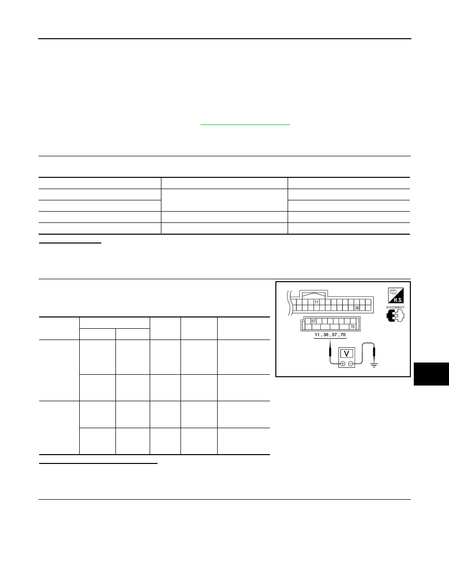
2.
CHECK POWER SUPPLY CIRCUIT
1. Turn ignition switch OFF.
2. Disconnect BCM.
3. Check voltage between BCM harness connector and ground.
Is the measurement value normal?
YES
>> GO TO 3
NO
>> Repair or replace harness.
3.
CHECK GROUND CIRCUIT
Terminal No.
Signal name
Fuses and fusible link No.
57
Battery power supply
21 (10A)
70
G (50A)
11
Ignition ACC or ON
4 (10A)
38
Ignition ON or START
1 (10A)
Connector
Terminals
Power
source
Condition
Voltage (V) (Ap-
prox.)
(+)
(-)
M18
11
Ground
ACC
power
supply
Ignition
switch
ACC or
ON
Battery voltage
38
Ground
Ignition
power
supply
Ignition
switch ON
or START
Battery voltage
M20
57
Ground
Battery
power
supply
Ignition
switch
OFF
Battery voltage
70
Ground
Battery
power
supply
Ignition
switch
OFF
Battery voltage
LIIA2415E
August 2012
2012 Pathfinder
Нет комментариевНе стесняйтесь поделиться с нами вашим ценным мнением.
Текст