Nissan Pathfinder (2012 year). Instruction — part 362
EXL-12
< SYSTEM DESCRIPTION >
AUTO LIGHT SYSTEM
AUTO LIGHT SYSTEM
System Diagram
INFOID:0000000007355112
System Description
INFOID:0000000007355113
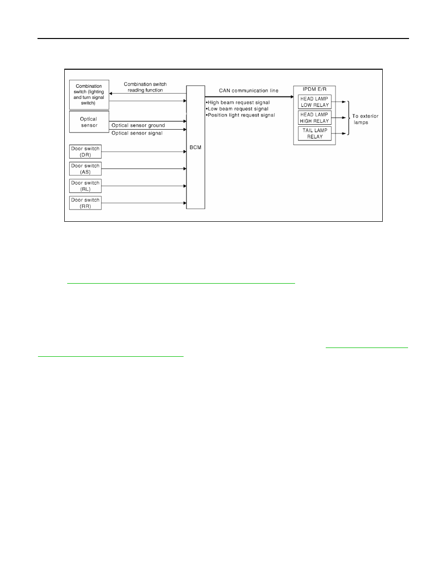
The auto light control system has an optical sensor that detects outside brightness.
When the lighting switch is in AUTO position, it automatically turns ON/OFF the parking, license plate, tail and
headlamps in accordance with the ambient light. Sensitivity can be adjusted in four steps. For the details,
BCS-21, "HEADLAMP : CONSULT Function (BCM - HEAD LAMP)"
AUTO LIGHT OPERATION
The auto light system operates the low beam and high beam headlamps, parking lamps, tail lamps and license
plate lamps. The BCM monitors the combination switch (lighting and turn signal switch) position as a part of
the BCM combination switch reading function. When the lighting switch is in the AUTO position, the BCM auto-
matically turns the lamps ON/OFF according to ambient light brightness.
NOTE:
Timing for when lamps turn ON/OFF can be changed by the CONSULT. Refer to
CONSULT Function (BCM - HEAD LAMP)"
AWLIA1910GB
August 2012
2012 Pathfinder
AUTO LIGHT SYSTEM
EXL-13
< SYSTEM DESCRIPTION >
C
D
E
F
G
H
I
J
K
M
A
B
EXL
N
O
P
Component Parts Location
INFOID:0000000007355114
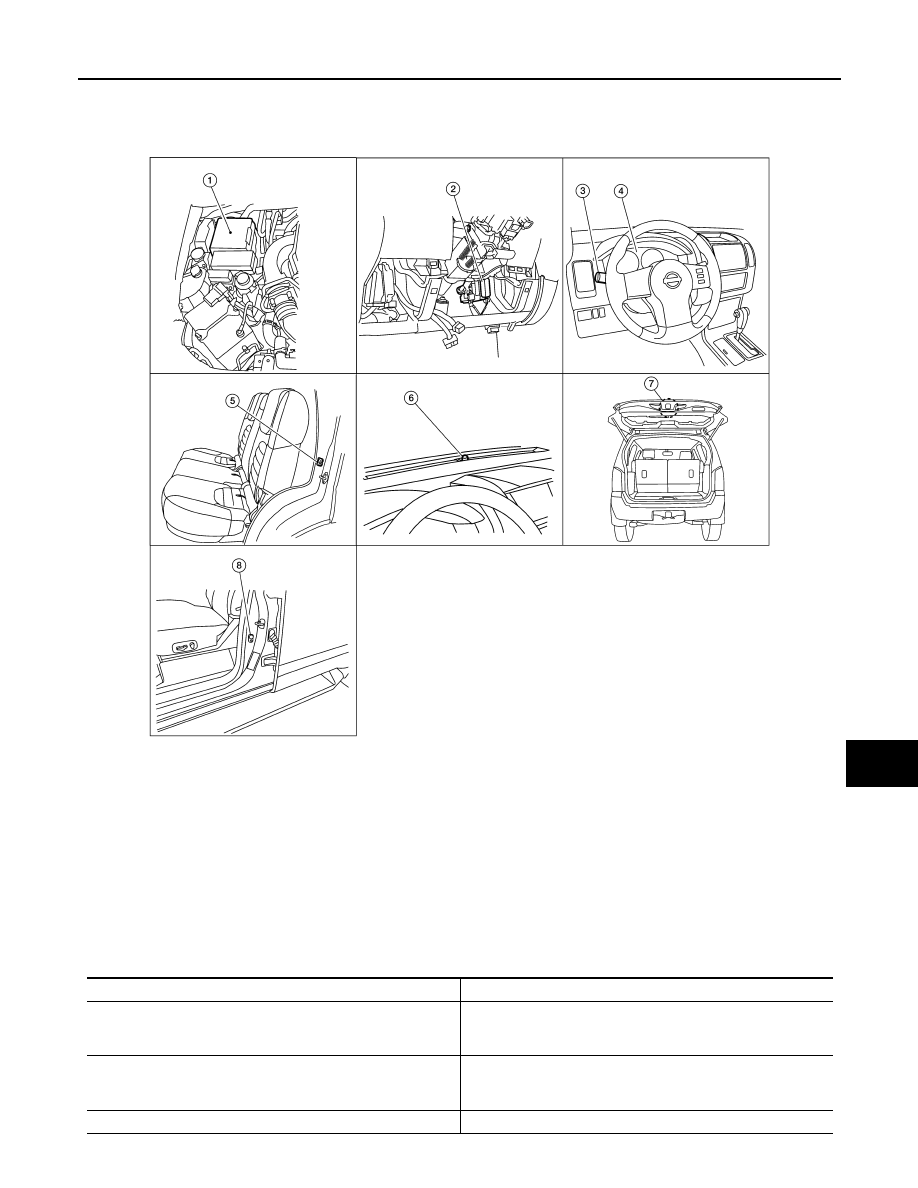
Component Description
INFOID:0000000007355115
1.
IPDM E/R E122, E123, E124
2.
BCM M18, M19, M20 (view with lower
instrument panel LH removed)
3.
Combination switch (lighting and turn
signal switch) M28
4.
Combination meter M24
5.
Rear door switch
LH B18
RH B116
6.
Optical sensor M145
7.
Back door latch (door ajar switch)
D502
8.
Front door switch
LH B8
RH B108
WKIA4959E
Part name
Description
BCM
BCM (Body Control Module) controls auto light operation accord-
ing to signals from optical sensor, lighting switch, door switches,
and ignition switch.
IPDM E/R
IPDM E/R (Intelligent Power Distribution Module Engine Room)
operates parking, license plate, tail and headlamps according to
CAN communication signals from BCM.
Combination switch (lighting switch)
The lighting switch outputs lighting requests to the BCM.
August 2012
2012 Pathfinder
EXL-14
< SYSTEM DESCRIPTION >
AUTO LIGHT SYSTEM
Optical sensor
Optical sensor detects ambient brightness and converts light
(lux) to voltage, then sends the optical sensor signal to BCM.
Door switches
Provides door OPEN input to BCM for auto light timer.
August 2012
2012 Pathfinder
FRONT FOG LAMP
EXL-15
< SYSTEM DESCRIPTION >
C
D
E
F
G
H
I
J
K
M
A
B
EXL
N
O
P
FRONT FOG LAMP
System Diagram
INFOID:0000000007355116
System Description
INFOID:0000000007355117
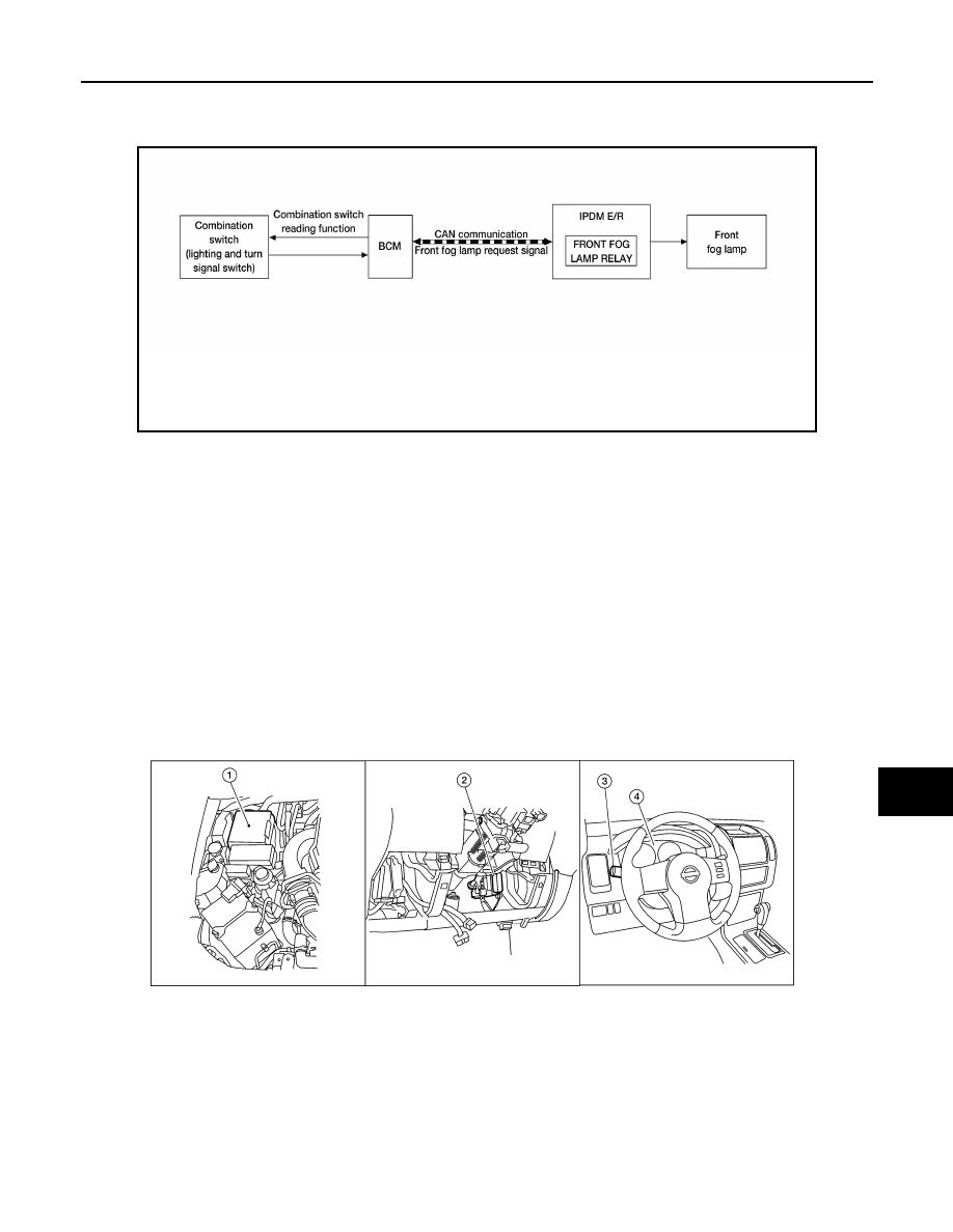
The front fog lamps are activated with the combination switch (lighting and turn signal switch). The lighting
switch signal to the BCM is monitored with the BCM combination switch reading function. When the fog lamps
are turned ON with the lighting switch, the BCM sends a front fog lamp request signal via CAN communication
lines to the IPDM E/R. The IPDM E/R grounds the front fog lamp relay coil to activate the front fog lamps.
FRONT FOG LAMP OPERATION
When the lighting switch is in front fog lamp ON position and also in 1ST or 2ND position or AUTO position
(headlamp is ON), the BCM detects FR FOG ON and the HEAD LAMP1, 2 ON or the AUTO LIGHT ON. The
BCM sends a front fog lamp request ON signal via the CAN communication lines to the IPDM E/R. The IPDM
E/R then turns ON the front fog lamp relay sending power to the front fog lamps.
Component Parts Location
INFOID:0000000007355118
AWLIA1719GB
1.
IPDM E/R E122, E123, E124
2.
BCM M18, M20 (view with lower instru-
ment panel LH removed)
3.
Combination switch (lighting and turn
signal switch) M28
4.
Combination meter M24
WKIA4960E
August 2012
2012 Pathfinder

EXL-16
< SYSTEM DESCRIPTION >
FRONT FOG LAMP
Component Description
INFOID:0000000007355119
Part name
Description
BCM
• Receives lighting switch requests via BCM combination switch
reading function.
• Sends headlamp high/low request signal to the IPDM E/R.
IPDM E/R
Activates the front fog lamp relay upon request from the BCM.
Combination switch (lighting and turn signal switch)
Outputs lighting requests to the BCM.
August 2012
2012 Pathfinder
TURN SIGNAL AND HAZARD WARNING LAMPS
EXL-17
< SYSTEM DESCRIPTION >
C
D
E
F
G
H
I
J
K
M
A
B
EXL
N
O
P
TURN SIGNAL AND HAZARD WARNING LAMPS
System Diagram
INFOID:0000000007355120
System Description
INFOID:0000000007355121
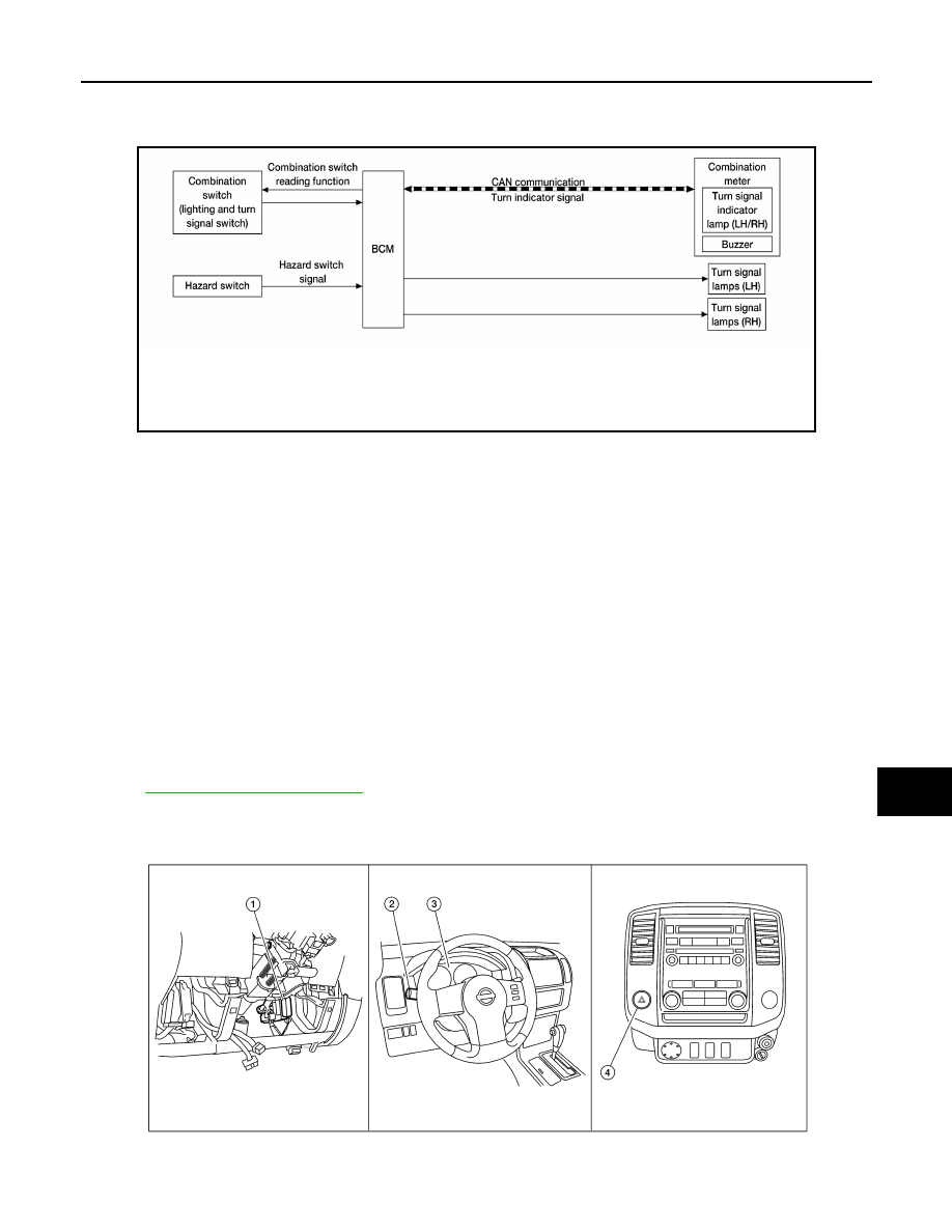
TURN SIGNAL OPERATION
When the turn signal switch is in LH or RH position with the ignition switch in ON position, the BCM detects the
TURN RH or TURN LH ON request. The BCM outputs the flasher signal to the respective turn signal lamp.
The BCM also sends a turn indicator signal ON request via the CAN communication lines to the combination
meter. The combination meter then activates the appropriate turn signal indicator and audible buzzer.
HAZARD LAMP OPERATION
When the hazard switch is in ON position, the BCM detects the hazard switch signal ON. The BCM outputs the
flasher signal (right and left). The BCM sends a hazard indicator signal ON request via the CAN communica-
tion lines to the combination meter. The combination meter then activates the hazard indicator and audible
buzzer.
REMOTE KEYLESS ENTRY OPERATION
The remote keyless entry receiver transmits a hazard request signal to the BCM, then BCM controls hazard
lamps.
.
Component Parts Location
INFOID:0000000007355122
AWLIA1721GB
AWLIA1683ZZ
August 2012
2012 Pathfinder

EXL-18
< SYSTEM DESCRIPTION >
TURN SIGNAL AND HAZARD WARNING LAMPS
Component Description
INFOID:0000000007355123
1.
BCM M18, M20 (view with lower instru-
ment panel LH removed)
2.
Combination switch (lighting and turn
signal switch) M28
3.
Combination meter M24
4.
Hazard switch M55
Part name
Description
BCM
Controls turn signal and hazard flasher operation.
Combination switch (lighting and turn signal switch)
Lighting and turn signal switch requests are output to the BCM.
Hazard switch
Hazard flasher request signal is output to the BCM.
Combination meter
Outputs turn and hazard indicator as requested by the BCM.
August 2012
2012 Pathfinder
PARKING, LICENSE PLATE AND TAIL LAMPS
EXL-19
< SYSTEM DESCRIPTION >
C
D
E
F
G
H
I
J
K
M
A
B
EXL
N
O
P
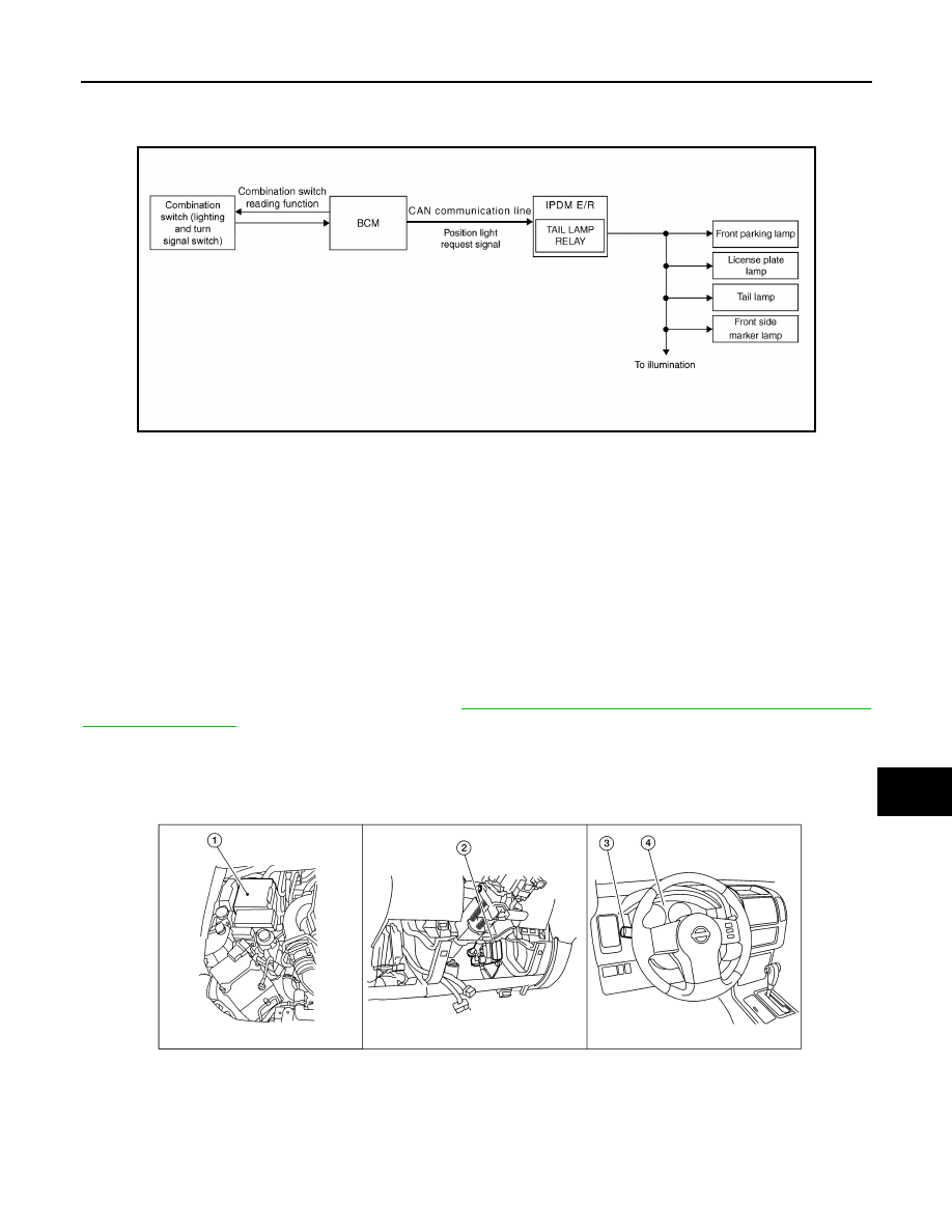
PARKING, LICENSE PLATE AND TAIL LAMPS
System Diagram
INFOID:0000000007355124
System Description
INFOID:0000000007355125
PARKING, LICENSE PLATE AND TAIL LAMPS OPERATION
When the lighting switch is in 1ST position, BCM detects the LIGHTING SWITCH 1ST POSITION ON. The
BCM sends a parking light ON request via the CAN communication lines to the IPDM E/R. The IPDM E/R then
activates the tail lamp relay which sends power to the parking and instrument illumination circuits.
EXTERIOR LAMP BATTERY SAVER CONTROL
With the combination switch (lighting and turn signal switch) in the 2ND position and the ignition switch is
turned from ON or ACC to OFF, the battery saver feature is activated.
Under this condition, the headlamps remain illuminated for 5 minutes (early production) or 45 seconds (late
production) unless the lighting switch position is changed. If the lighting switch position is changed, then the
headlamps are turned off.
This setting can be changed by CONSULT. Refer to
BCS-24, "BATTERY SAVER : CONSULT Function (BCM
Component Parts Location
INFOID:0000000007355126
ABLIA2837GB
1.
IPDM E/R E121, E122, E123, E124
2.
BCM M18, M20 (view with lower instru-
ment panel LH removed)
3.
Combination switch (lighting and turn
signal switch) M28
4.
Combination meter M24
WKIA4963E
August 2012
2012 Pathfinder
Нет комментариевНе стесняйтесь поделиться с нами вашим ценным мнением.
Текст