Nissan Pathfinder (2012 year). Instruction — part 385
FAX-12
< UNIT DISASSEMBLY AND ASSEMBLY >
DRIVE SHAFT
UNIT DISASSEMBLY AND ASSEMBLY
DRIVE SHAFT
VQ40DE
VQ40DE : Disassembly and Assembly
INFOID:0000000007357681
DISASSEMBLY
Final Drive Side
1. Mount the drive shaft in a vise.
CAUTION:
When mounting the drive shaft in a vise, use copper or aluminum plates between the vise and the
drive shaft.
2. Remove boot bands and slide the boot back.
3. Put matching marks on housing and shaft before separating joint assembly.
CAUTION:
Use paint or similar substance for matching marks. Do not scratch the surfaces.
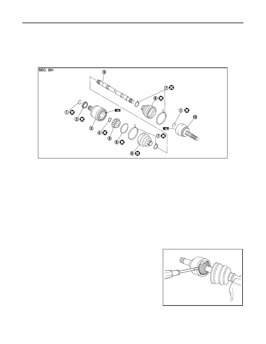
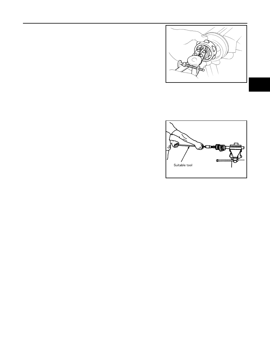
4. Remove the stopper ring with a suitable tool as shown, and pull
the housing off.
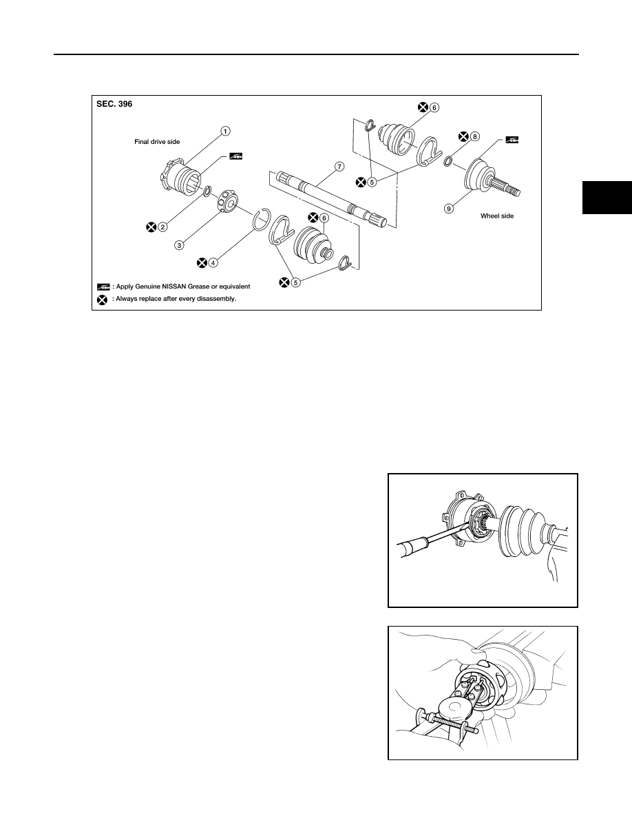
1.
Circlip
2.
Dust cover
3.
Housing
4.
Snap ring
5.
Ball cage, steel ball and inner race assembly
6.
Stopper ring
7.
Boot band
8.
Boot
9.
Shaft
10.
Joint sub-assembly
WDIA0342E
SFA476
August 2012
2012 Pathfinder
DRIVE SHAFT
FAX-13
< UNIT DISASSEMBLY AND ASSEMBLY >
C
E
F
G
H
I
J
K
L
M
A
B
FAX
N
O
P
5. Remove the snap ring, then remove the ball cage, steel ball,
inner race assembly from the shaft.
6. Remove the boot from the shaft.
7. Remove circlip and dust cover from housing.
8. Clean the old grease off of the housing using paper towels.
Wheel Side
1. Mount the drive shaft in a vise.
CAUTION:
When mounting the drive shaft in a vise, use copper or aluminum plates between the vise and the
drive shaft.
2. Remove the boot bands and slide the boot back.
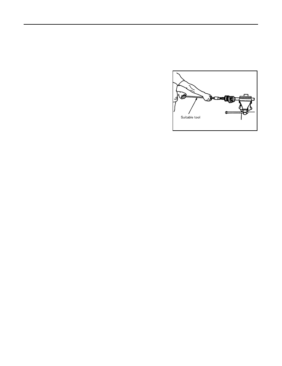
3. Screw a sliding hammer or suitable tool 30 mm (1.18 in) or more
into threaded part of joint sub-assembly. Pull joint sub-assembly
off of shaft as shown.
NOTE:
Align the sliding hammer and shaft and remove the joint sub-
assembly by pulling directly.
CAUTION:
• If the joint sub-assembly cannot be removed after five or
more unsuccessful attempts, replace the entire drive shaft
assembly.
4. Remove boot from the shaft.
5. Remove circlip from the shaft.
6. While rotating the ball cage, clean the old grease off of the joint sub-assembly using paper towels.
INSPECTION AFTER DISASSEMBLY
Shaft
• Replace the shaft if there is any bending, cracking, or other damage.
Joint Sub-assembly
• Check for any rough rotation or unusual axial looseness.
• Clean any foreign material from inside the joint sub-assembly.
• Check for any compression scars, cracks, or fractures.
CAUTION:
If any irregular conditions are found in the joint sub-assembly components, replace the entire joint
sub-assembly.
Housing
NOTE:
Housing, ball cage, steel ball, and inner race are in a set.
• Check for any compression scars, cracks, fractures, or unusual wear on the ball rolling surface.
• Check for any deformation of the boot installation components.
Ball Cage
• Check the sliding surface for any compression scars, cracks, or fractures of sliding surface.
Steel Ball
• Check for any compression scars, cracks, fractures, or unusual wear.
Inner Race
• Check the ball sliding surface for any compression scars, cracks, or fractures.
• Check for any damage to the serrated part.
ASSEMBLY
SFA514A
SDIA0606E
August 2012
2012 Pathfinder
FAX-14
< UNIT DISASSEMBLY AND ASSEMBLY >
DRIVE SHAFT
Final Drive Side
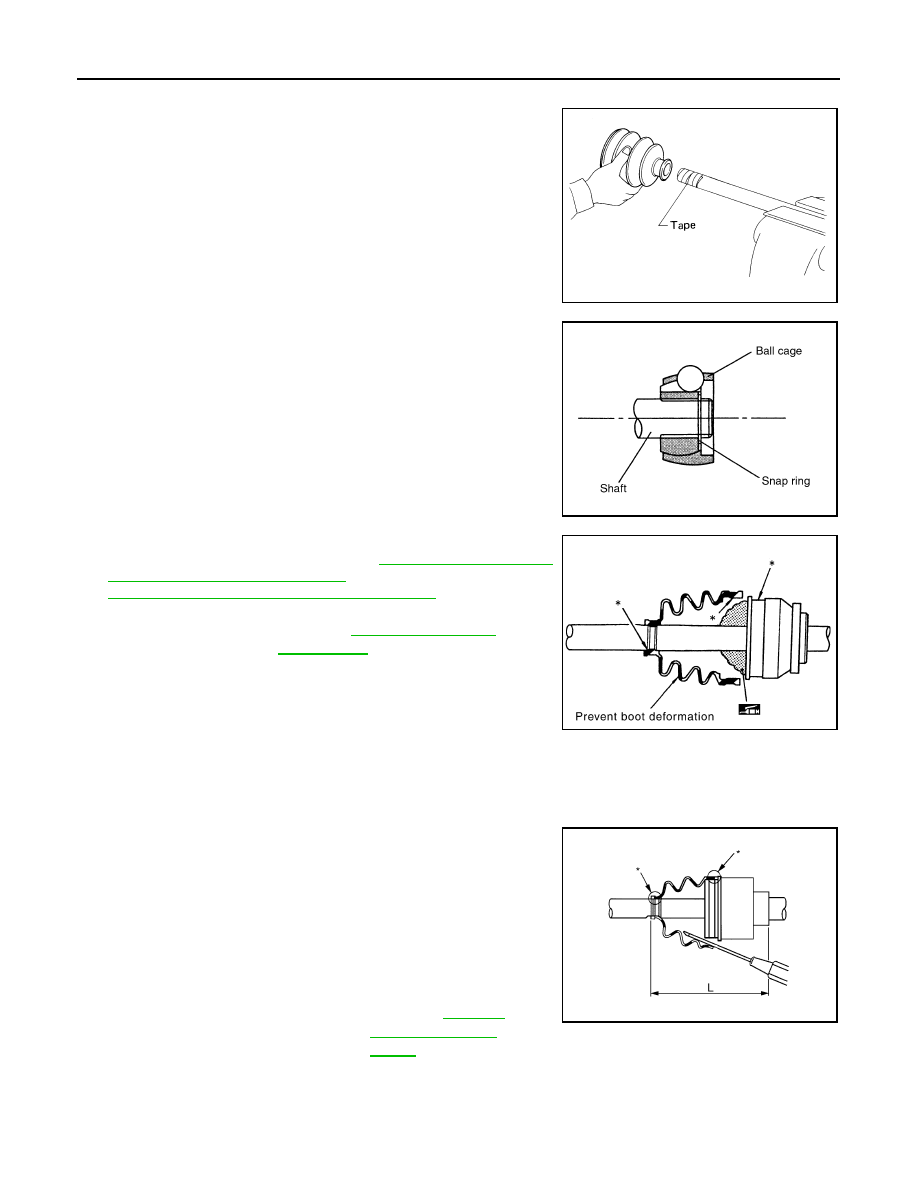
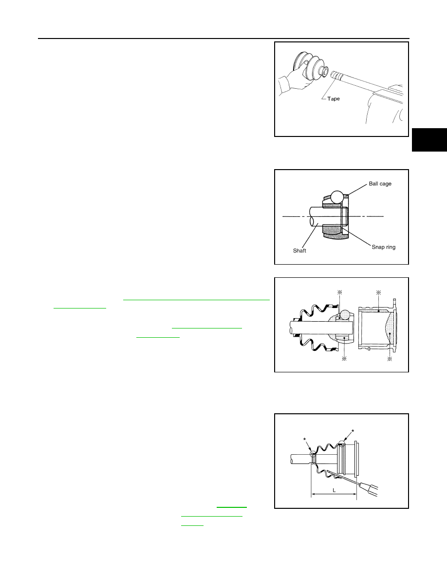
1. Wrap the serrated part of the shaft with tape. Install the boot
band and boot to shaft.
NOTE:
Discard the old boot band and boot and use a new one for
assembly.
2. Remove the tape wound around the serrated part of the shaft.
3. Install the ball cage, steel ball, and inner race assembly on the
shaft, and secure them using the snap ring.
NOTE:
Discard the old snap ring and use a new one for assembly.
4. Insert the specified quantity of Genuine NISSAN Grease or
equivalent, into the housing. Refer to
CANADA : Fluids and Lubricants"
(United States and Canada),
MA-20, "FOR MEXICO : Fluids and Lubricants"
CAUTION:
If grease adheres to the boot mounting surface (indicated
by * marks) on shaft and housing, boot may come off.
Remove all grease from surfaces.
5. Install the stopper ring onto the housing.
CAUTION:
• Do not reuse stopper rings.
• Make sure that housing and stopper ring are fully engaged.
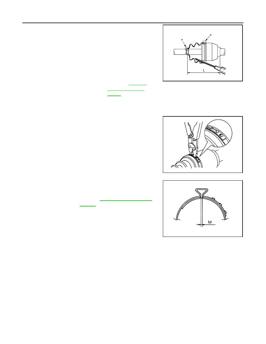
6. Install the boot securely into the grooves (indicated by * marks)
as shown.
CAUTION:
If there is grease on boot mounting surfaces (indicated by *
marks) of shaft and housing, boot may come off. Remove
all grease from surfaces.
7. Check that the boot installation length (L) is the length indicated
below. Insert a suitable tool into the large side of boot. Bleed air
from boot to prevent boot deformation.
CAUTION:
• The boot may break if the boot installation length is less than the specified value.
• Do not to touch the tip of the suitable tool to the inside of the boot.
SFA800
SDIA1125E
Grease capacity
: Refer to
SDIA1446E
Boot installation length (L)
: Refer to
.
AWDIA0681GB
August 2012
2012 Pathfinder
DRIVE SHAFT
FAX-15
< UNIT DISASSEMBLY AND ASSEMBLY >
C
E
F
G
H
I
J
K
L
M
A
B
FAX
N
O
P
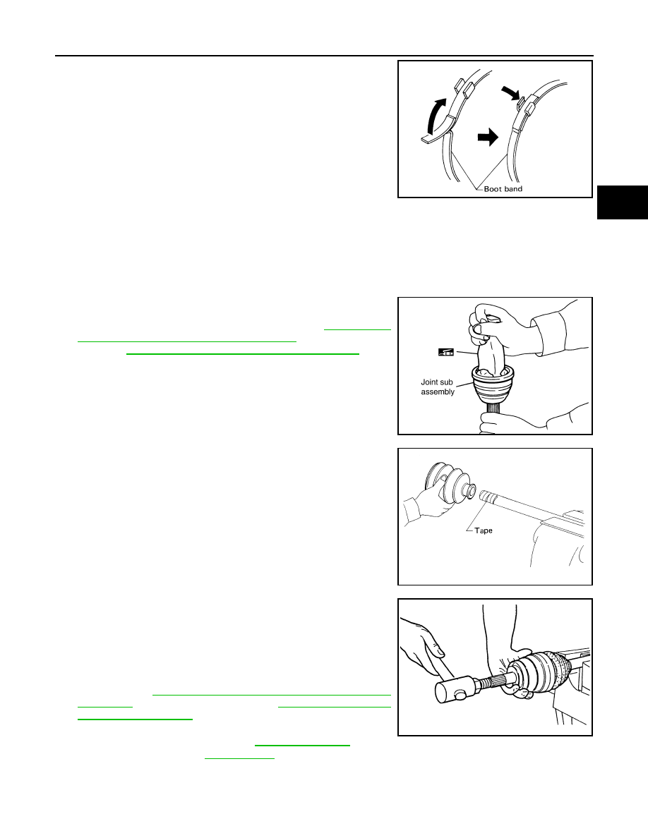
8. Secure the big and small ends of the boot with the new boot
bands as shown.
NOTE:
Discard not reuse boot bands.
9. Secure housing and shaft and then make sure that they are in the correct position when rotating boot. Use
a new boot band if the boot band needs to be loosened to reposition the boot.
10. Install circlip and dust cover to housing.
NOTE:
Do not reuse circlip and dust cover.
Wheel Side
1. Insert the Genuine NISSAN Grease or equivalent, into the joint
sub-assembly serration hole until the grease begins to ooze
from the ball groove and serration hole. Refer to
USA AND CANADA : Fluids and Lubricants"
(United States and
Canada),
MA-20, "FOR MEXICO : Fluids and Lubricants"
(Mex-
ico). After inserting the grease, use a shop cloth to wipe off the
grease that has oozed out.
2. Wrap the serrated part of the shaft with tape. Install the boot
band and boot onto the shaft. Do not damage the boot.
NOTE:
Discard the old boot band and boot and use a new one for
assembly.
3. Remove the protective tape wound around the serrated part of
the shaft.
4. Attach the circlip to the shaft. The circlip must fit securely into
the shaft groove. Attach the nut to the joint sub-assembly.
Use a soft hammer to press-fit the circlip.
NOTE:
Discard the old circlip and use a new one for assembly.
5. Insert the specified quantity of Genuine NISSAN Grease or
equivalent, into the joint sub-assembly and the large end of the
boot. Refer to
MA-18, "FOR USA AND CANADA : Fluids and
(Mexico).
SFA395
SDIA1127E
SFA800
Grease capacity
.
RAC0049D
August 2012
2012 Pathfinder
FAX-16
< UNIT DISASSEMBLY AND ASSEMBLY >
DRIVE SHAFT
6. Install the boot securely into the grooves (indicated by the *
marks) as shown.
CAUTION:
If there is grease on the boot mounting surfaces (indicated
by the * marks) of the shaft and joint sub-assembly, the
boot may come off. Remove all grease from the drive shaft
surfaces.
7. Check that the boot installation length (L) is the specified length.
Insert a suitable tool into the large side of the boot. Bleed the air
from the boot to prevent boot deformation.
CAUTION:
• The boot may break if the boot installation length is less than the specified length.
• Do not contact inside surface of boot with the tip of the suitable tool.
8. Secure large and small ends of the boot using new boot bands
using a boot band crimping tool as shown.
NOTE:
Do not reuse boot bands.
• Secure boot band so that dimension (M) meets specification
as shown.
9. After installing the housing to the shaft, rotate the boot to check
that it is positioned correctly. If the boot is not positioned cor-
rectly, remove the old boot bands then reposition the boot and
secure the boot with new boot bands.
VK56DE
Boot installation length (L)
: Refer to
.
Tool number : KV40107300 ( — )
JPDIF0142ZZ
RAC1133D
Dimension (M)
: Refer to
.
DSF0047D
August 2012
2012 Pathfinder
DRIVE SHAFT
FAX-17
< UNIT DISASSEMBLY AND ASSEMBLY >
C
E
F
G
H
I
J
K
L
M
A
B
FAX
N
O
P
VK56DE : Disassembly and Assembly
INFOID:0000000007357682
DISASSEMBLY
Final Drive Side
1. Mount the drive shaft in a vise.
CAUTION:
When mounting the drive shaft in a vise, use copper or aluminum plates between the vise and the
drive shaft.
2. Remove the boot bands.
3. Remove the stopper ring with a suitable tool as shown, and pull
the housing off.
4. Remove the snap ring, then remove the ball cage, steel ball,
inner race assembly from the drive shaft.
5. Remove the boot from the drive shaft.
1. Sliding joint housing
2. Snap ring
3. Ball cage, steel ball, inner race assembly
4. Stopper ring
5. Boot band
6. Boot
7. Drive shaft
8. Circlip
9. Joint sub-assembly
WDIA0054E
SRA249A
SFA514A
August 2012
2012 Pathfinder
FAX-18
< UNIT DISASSEMBLY AND ASSEMBLY >
DRIVE SHAFT
6. Remove any old grease on the housing using paper towels.
Wheel Side
1. Mount the drive shaft in a vise.
CAUTION:
When mounting the drive shaft in a vise, use copper or aluminum plates between the vise and the
drive shaft.
2. Remove the boot bands, then remove the boot from the joint sub-assembly.
3. Screw a suitable drive shaft puller 30 mm (1.18 in) or more into
the threaded part of the joint sub-assembly. Pull the joint sub-
assembly off of the drive shaft as shown.
NOTE:
Align the sliding hammer and drive shaft and remove the joint
sub-assembly by pulling directly.
CAUTION:
• If the joint sub-assembly cannot be removed after five or
more attempts, replace the drive shaft and joint sub-
assembly as a set.
4. Remove the boot from the drive shaft.
5. Remove the circlip from the drive shaft.
6. While rotating the ball cage, remove any old grease from the joint sub-assembly using paper towels.
INSPECTION AFTER DISASSEMBLY
Drive Shaft
• Replace the drive shaft if there is any runout, cracking, or other damage.
Joint Sub-assembly
• Check for any rough rotation or unusual axial looseness.
• Clean any foreign material from inside the joint sub-assembly.
• Check for any compression scars, cracks, or fractures.
CAUTION:
If any defective conditions are found in the joint sub-assembly components, replace the entire joint
sub-assembly.
Sliding Joint Side Housing
• Check for any compression scars, cracks, fractures, or unusual wear on the ball rolling surface.
• Check for any damage to the drive shaft screws.
• Check for any deformation of the boot installation components.
Ball Cage
• Check the sliding surface for any compression scars, cracks, or fractures.
Steel Ball
• Check for any compression scars, cracks, fractures, or unusual wear.
Inner Race
• Check the ball sliding surface for any compression scars, cracks, or fractures.
• Check for any damage to the serrated part.
CAUTION:
If any defective conditions are found, install a new housing, ball cage, steel ball, and inner race as a
set.
ASSEMBLY
Final Drive Side
SDIA0606E
August 2012
2012 Pathfinder
DRIVE SHAFT
FAX-19
< UNIT DISASSEMBLY AND ASSEMBLY >
C
E
F
G
H
I
J
K
L
M
A
B
FAX
N
O
P
1. Wrap the serrated part of the drive shaft with tape. Install the
boot band and boot to drive shaft.
NOTE:
Discard the old boot band and boot and use a new one for
assembly.
2. Remove the tape wound around the serrated part of the drive shaft.
3. Install the ball cage, steel ball, and inner race assembly on the
drive shaft, and secure them tightly using the snap ring.
NOTE:
Discard the old snap ring and use a new one for assembly.
4. Insert the specified quantity of Genuine NISSAN Grease or
equivalent, onto the housing (indicated by * marks), and install it
onto shaft. Refer to
MA-18, "FOR USA AND CANADA : Fluids
.
5. Install the stopper ring onto the housing.
6. After installation, pull on the shaft to check engagement between the sliding joint and the stopper ring.
7. Install the boot securely into the grooves (indicated by * marks)
as shown.
CAUTION:
If there is grease on boot mounting surfaces (indicated by *
marks) of shaft and housing, boot may come off. Remove
all grease from surfaces.
8. Check that the boot installation length (L) is the length indicated
below. Insert a suitable tool into the large end of the boot. Bleed
air from the boot to prevent boot deformation.
CAUTION:
• The boot may break if the boot installation length is less than the specified value.
• Do not to touch the tip of the suitable tool to the inside of the boot.
SFA800
SDIA1125E
Grease capacity
: Refer to
.
RAC0678D
Boot installation length (L)
.
WDIA0287E
August 2012
2012 Pathfinder
Нет комментариевНе стесняйтесь поделиться с нами вашим ценным мнением.
Текст