Nissan Pathfinder (2012 year). Instruction — part 384
FAX-4
< PREPARATION >
PREPARATION
PREPARATION
PREPARATION
Special Service Tool
INFOID:0000000007357674
The actual shapes of Kent-Moore tools may differ from those of special service tools illustrated here.
Commercial Service Tool
INFOID:0000000007357675
Tool number
(Kent-Moore No.)
Tool name
Description
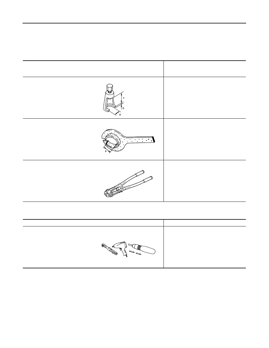
ST29020001
(J-24319-01)
Gear arm puller
Removing ball joint for steering knuckle
a: 34 mm (1.34 in)
b: 6.5 mm (0.256 in)
c: 61.5 mm (2.421 in)
KV38105500
(J-33904)
Protector
Installing drive shaft
a: 32 mm (1.26 in) dia
KV40107300
(
—
)
Boot band crimping tool
Installing boot bands
NT694
ZZA0835D
ZZA1229D
Tool name
Description
Power tools
Loosening nuts, screws and bolts
PIIB1407E
August 2012
2012 Pathfinder
NOISE, VIBRATION, AND HARSHNESS (NVH) TROUBLESHOOTING
FAX-5
< SYMPTOM DIAGNOSIS >
C
E
F
G
H
I
J
K
L
M
A
B
FAX
N
O
P
SYMPTOM DIAGNOSIS
NOISE, VIBRATION, AND HARSHNESS (NVH) TROUBLESHOOTING
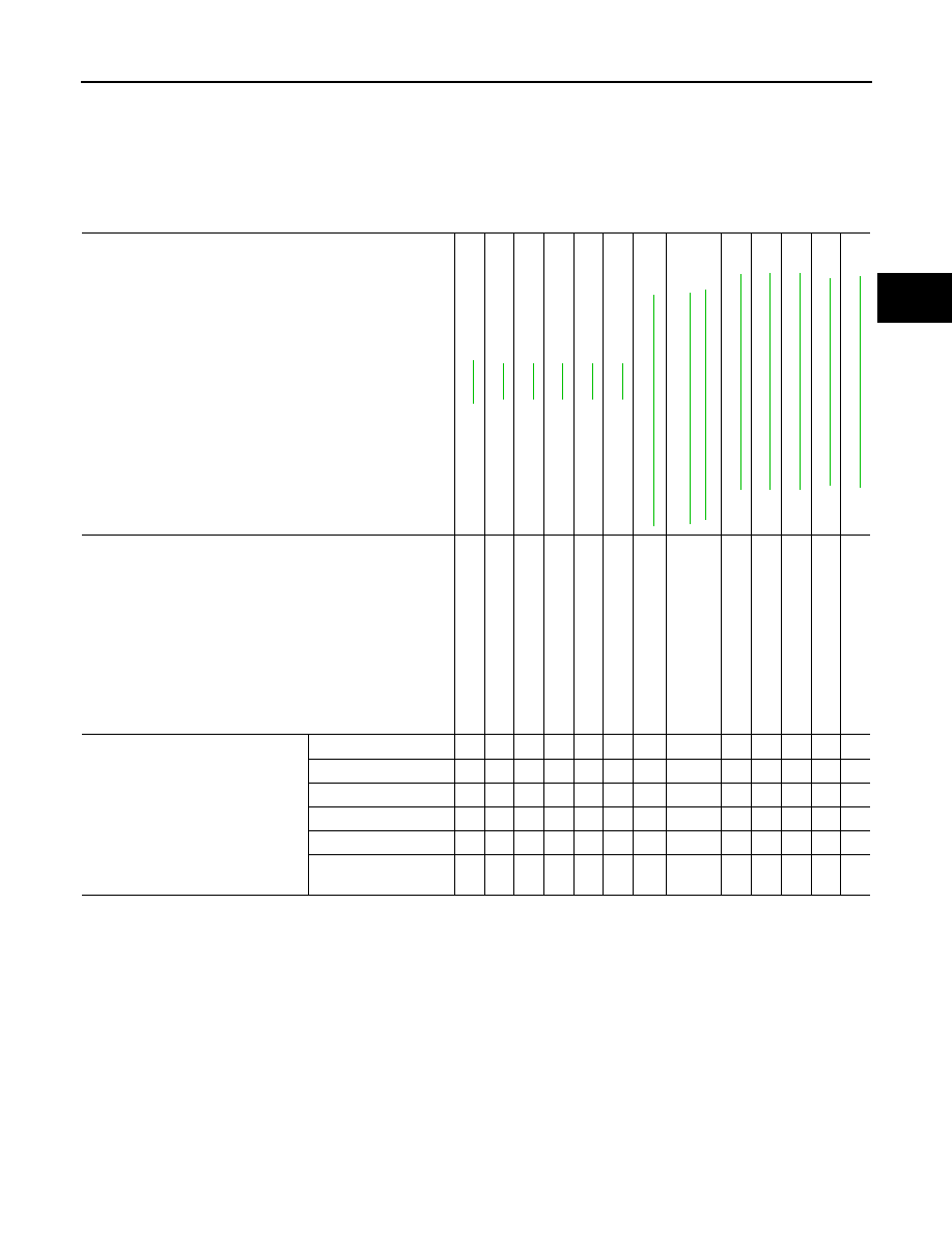
NVH Troubleshooting Chart
INFOID:0000000007357676
Use the chart below to help you find the cause of the symptom. If necessary, repair or replace these parts.
×
: Applicable
Reference page
(2
F1
31
0)
(R18
0A)
(M
20
5)
Possible cause and SUSPECTED PARTS
Ex
ce
ss
iv
e j
oi
nt an
gl
e
Jo
in
t s
lid
in
g re
si
st
an
ce
Imb
al
anc
e
Im
pro
pe
r in
st
al
lat
ion
,
lo
ose
ness
P
art
s interference
W
he
el be
arin
g da
ma
ge
PR
OP
EL
LE
R
S
H
A
F
T
FRO
N
T FINAL DRIVE
S
U
S
PENSION
TI
RE
S
ROAD W
H
EEL
BR
AK
E
S
S
T
EERING
Symptom
Noise
×
×
×
×
×
×
×
×
×
×
×
Shake
×
×
×
×
×
×
×
×
×
×
Vibration
×
×
×
×
×
×
×
×
×
Shimmy
×
×
×
×
×
×
×
×
Shudder
×
×
×
×
×
×
×
×
×
Poor quality ride or
handling
×
×
×
×
×
×
August 2012
2012 Pathfinder
FAX-6
< PERIODIC MAINTENANCE >
WHEEL HUB
PERIODIC MAINTENANCE
WHEEL HUB
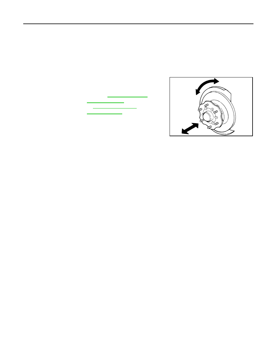
On-Vehicle Inspection and Service
INFOID:0000000007357677
Make sure the mounting conditions (looseness, backlash) of each component and component status (wear,
damage) are normal.
WHEEL BEARING INSPECTION
• Move wheel hub in the axial direction by hand. Make sure there is
no looseness of wheel bearing.
• Rotate wheel hub and make sure there is no unusual noise or
other irregular conditions. If there are any irregular conditions,
replace wheel hub and bearing assembly.
Axial end play limit : Refer to
SMA571A
August 2012
2012 Pathfinder
DRIVE SHAFT
FAX-7
< UNIT REMOVAL AND INSTALLATION >
C
E
F
G
H
I
J
K
L
M
A
B
FAX
N
O
P
UNIT REMOVAL AND INSTALLATION
DRIVE SHAFT
VQ40DE
VQ40DE : Removal and Installation
INFOID:0000000007357678
REMOVAL
1. Remove wheel and tire using power tool.
2. Remove rear engine under cover using power tool.
3. Remove wheel sensor harness from mount on knuckle, then disconnect wheel sensor harness connector.
CAUTION:
Do not pull on wheel sensor harness.
4. Remove wheel hub and bearing assembly. Refer to
FAX-10, "Removal and Installation"
• It is not necessary to remove wheel sensor from wheel hub when wheel hub is not being replaced.
• Carefully feed wheel sensor harness through hole in splash shield.
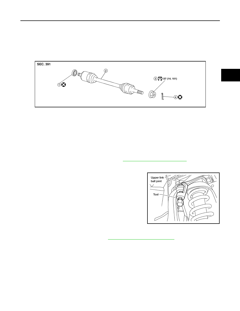
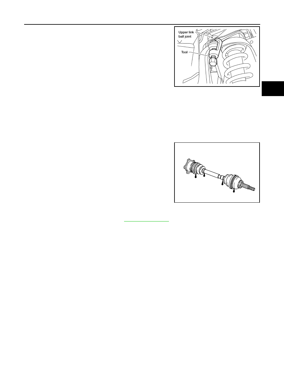
5. Separate upper link ball joint stud from steering knuckle using
Tool.
• Support lower link with jack.
6. Remove drive shaft assembly.
• Pry drive shaft front final drive using suitable tool.
• Remove differential side oil seal. Refer to
DLN-355, "Removal and Installation"
.
CAUTION:
• When removing drive shaft, do not apply an excessive angle to drive shaft joint. Also be careful
not to excessively extend slide joint.
INSPECTION AFTER REMOVAL
• Move joint up, down, left, right, and in axial direction. Check for any rough movement or significant loose-
ness.
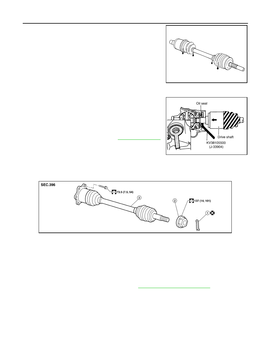
1.
Differential side oil seal
2.
Drive shaft
3.
Drive shaft lock nut
4.
Cotter pin
WDIA0341E
Tool number
: ST29020001 (J-24319-01)
WEIA0119E
August 2012
2012 Pathfinder
FAX-8
< UNIT REMOVAL AND INSTALLATION >
DRIVE SHAFT
• Check boot for cracks or other damage, and for grease leakage.
• If damaged, disassemble drive shaft to verify damage, and repair
or replace as necessary.
INSTALLATION
Installation is in the reverse order of removal.
• When installing drive shaft onto front final drive, use Tool to pre-
vent damage to the oil seal while inserting drive shaft. Slide drive
shaft sliding joint and tap with a hammer to install securely.
CAUTION:
Do not reuse the differential side oil seal.
• Tighten wheel nuts to specification. Refer to
VK56DE
VK56DE : Removal and Installation
INFOID:0000000007357679
REMOVAL
1. Remove wheel and tire using power tool.
2. Remove engine under cover using power tool.
3. Remove wheel sensor harness from mount on knuckle, then disconnect wheel sensor harness connector.
CAUTION:
Do not pull on wheel sensor harness.
4. Remove wheel hub and bearing assembly. Refer to
FAX-10, "Removal and Installation"
.
• It is not necessary to remove wheel sensor from wheel hub when wheel hub is not being replaced.
• Carefully feed wheel sensor harness through hole in splash shield.
SFA108A
Tool number
: KV38105500 (J-33904)
SDIA2615E
1.
Cotter pin
2.
Drive shaft nut
3.
Drive shaft
WDIA0329E
August 2012
2012 Pathfinder
DRIVE SHAFT
FAX-9
< UNIT REMOVAL AND INSTALLATION >
C
E
F
G
H
I
J
K
L
M
A
B
FAX
N
O
P
5. Separate upper link ball joint stud from steering knuckle using
Tool.
• Support lower link with jack.
6. Remove drive shaft mounting bolts from front final drive.
7. Remove drive shaft assembly.
CAUTION:
• When removing drive shaft, do not apply an excessive angle to drive shaft joint. Also be careful
not to excessively extend slide joint.
INSPECTION AFTER REMOVAL
• Move joint up, down, left, right, and in axial direction. Check for any rough movement or significant loose-
ness.
• Check boot for cracks or other damage, and for grease leakage.
• If damaged, disassemble drive shaft to verify damage, and repair
or replace as necessary.
INSTALLATION
Installation is in the reverse order of removal.
• Tighten wheel nuts to specification. Refer to
Tool number
: ST29020001 (J-24319-01)
WEIA0119E
RAA0030D
August 2012
2012 Pathfinder
FAX-10
< UNIT REMOVAL AND INSTALLATION >
WHEEL HUB
WHEEL HUB
Removal and Installation
INFOID:0000000007357680
REMOVAL
1. Remove wheel and tire using power tool.
2. Without disassembling the hydraulic lines, remove caliper torque member bolts using power tool. Then
reposition brake caliper aside with wire. Refer to
BR-42, "Removal and Installation of Brake Caliper and
CAUTION:
Do not press brake pedal while brake caliper is removed.
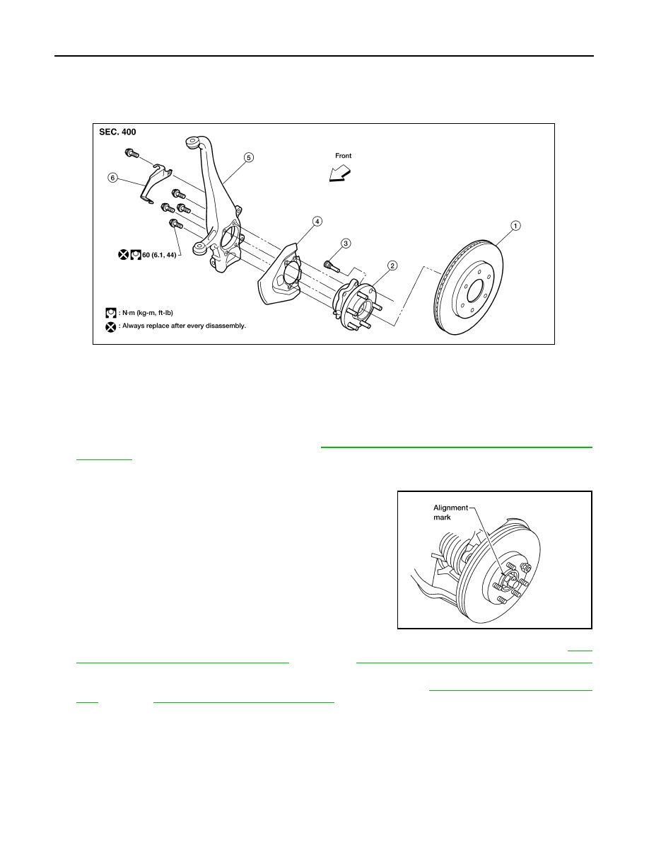
3. Put alignment mark on disc rotor and wheel hub and bearing
assembly, then remove disc rotor.
4. On 4WD models, remove cotter pin, then remove lock nut from drive shaft using power tool. Refer to
7, "VQ40DE : Removal and Installation"
FAX-8, "VK56DE : Removal and Installation"
(VK56DE).
5. Remove wheel sensor from wheel hub and bearing assembly. Refer to
BRC-110, "Removal and Installa-
(TYPE 1),
BRC-229, "Removal and Installation"
(TYPE 2).
• Inspect the wheel sensor O-ring, replace the wheel sensor assembly if damaged.
• Clean the wheel sensor hole and mounting surface with a suitable brake cleaner and clean lint-free
shop rag. Be careful that dirt and debris do not enter the axle bearing area.
• Apply a coat of suitable grease to the wheel sensor O-ring and mounting hole.
CAUTION:
Do not pull on the wheel sensor harness.
6. On 4WD models, separate drive shaft from wheel hub and bearing assembly.
7. Remove wheel hub and bearing assembly bolts using power tool.
1.
Disc rotor
2.
Wheel hub and bearing assembly
3.
Wheel stud
4.
Splash guard
5.
Steering knuckle
6.
Wheel sensor bracket
WDIA0228E
WDIA0044E
August 2012
2012 Pathfinder
WHEEL HUB
FAX-11
< UNIT REMOVAL AND INSTALLATION >
C
E
F
G
H
I
J
K
L
M
A
B
FAX
N
O
P
8. Remove splash guard and wheel hub and bearing assembly from steering knuckle.
• Carefully remove wheel sensor and harness through hole in splash guard.
INSPECTION AFTER REMOVAL
Check for deformity, cracks and damage on each part and replace if necessary.
INSTALLATION
Installation is in the reverse order of removal.
• Use new bolts when installing the wheel hub and bearing assembly.
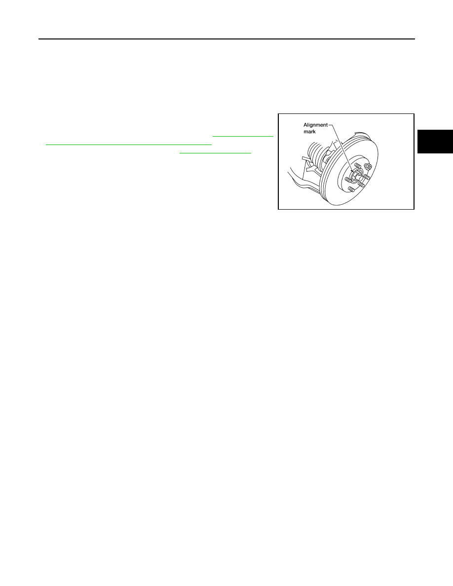
• When installing disc rotor on wheel hub and bearing assembly,
position the disc rotor according to alignment mark.
(When not using the alignment mark, refer to
and Installation of Brake Caliper and Disc Rotor"
.)
• When installing wheel and tire, refer to
WDIA0044E
August 2012
2012 Pathfinder
Нет комментариевНе стесняйтесь поделиться с нами вашим ценным мнением.
Текст